
The Hot-Spot Effect in PV Modules, Step by Step: How a Shaded Cell Gets Driven Down to −16.8 V
A fallen leaf, a bird dropping or a patch of dust can send the temperature of a single cell in a module soaring. At best the module loses power; at worst the backsheet burns through. This is what the industry calls the hot-spot effect.
Most people have heard that "a shaded cell turns from a generator into a load." But what actually happens in between? How does the voltage change? At what moment does the bypass diode turn on? And once it does, is the hot spot gone?
This article walks through the whole process from start to finish using one concrete worked example.
Assumptions for the worked example
A standard 144 half-cell module with 3 bypass diodes; each cell has Voc ≈ 0.7 V and Isc ≈ 8 A. To keep the arithmetic simple, cell voltage is taken as 0.7 V throughout.
1. Normal operation: the bypass diode is on standby
Start with the module's circuit. A 144 half-cell module is split into an upper half and a lower half, and each half contains 3 strings of 24 series-connected cells. Each upper string is connected in parallel with the corresponding lower string, and that pair is connected anti-parallel with one bypass diode in the junction box.
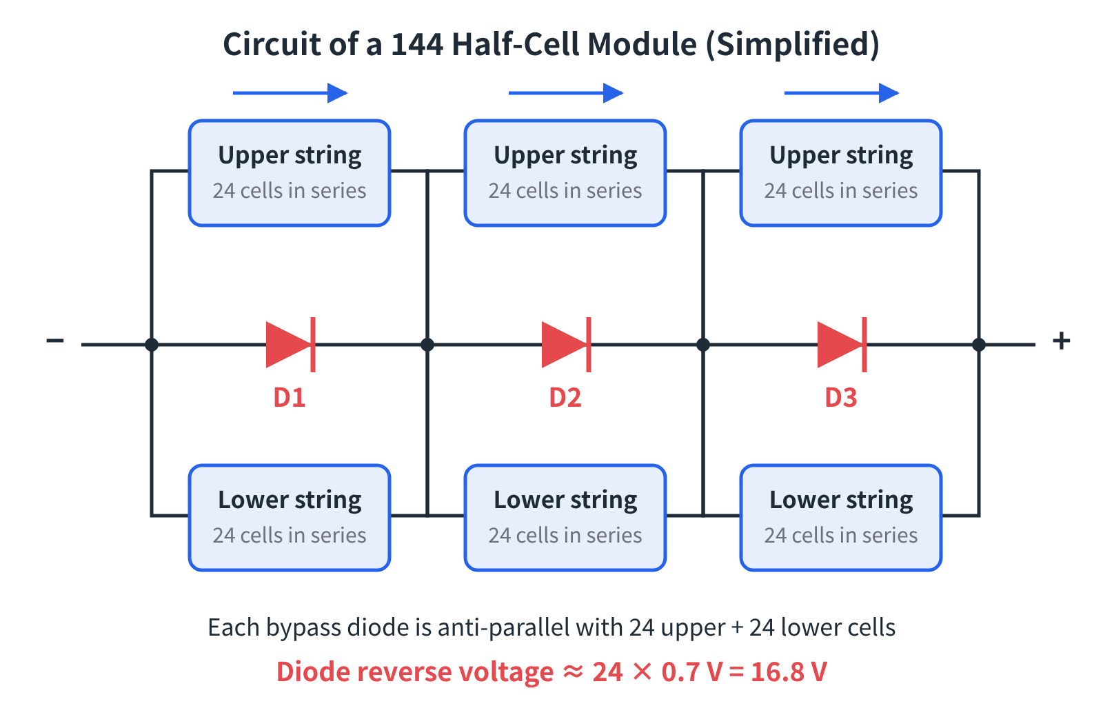
Figure 1 | Simplified circuit of a 144 half-cell module: each diode "watches over" 24 upper and 24 lower cells
When the module is generating normally:
- The cell strings deliver their output and all current flows through the cells;
- Because the diode is anti-parallel with the string, it sees a reverse voltage equal to the string voltage:
24 × 0.7 V = 16.8 V
A 16.8 V reverse bias is easy work for the diode. PV junction boxes generally use Schottky diodes; the model used in one leading manufacturer's 25 A junction box, for example, is rated for 45 V continuous reverse voltage, leaving plenty of margin.
So the diode is in reverse cut-off, carrying only a tiny reverse leakage current Is. For practical purposes it "isn't there."
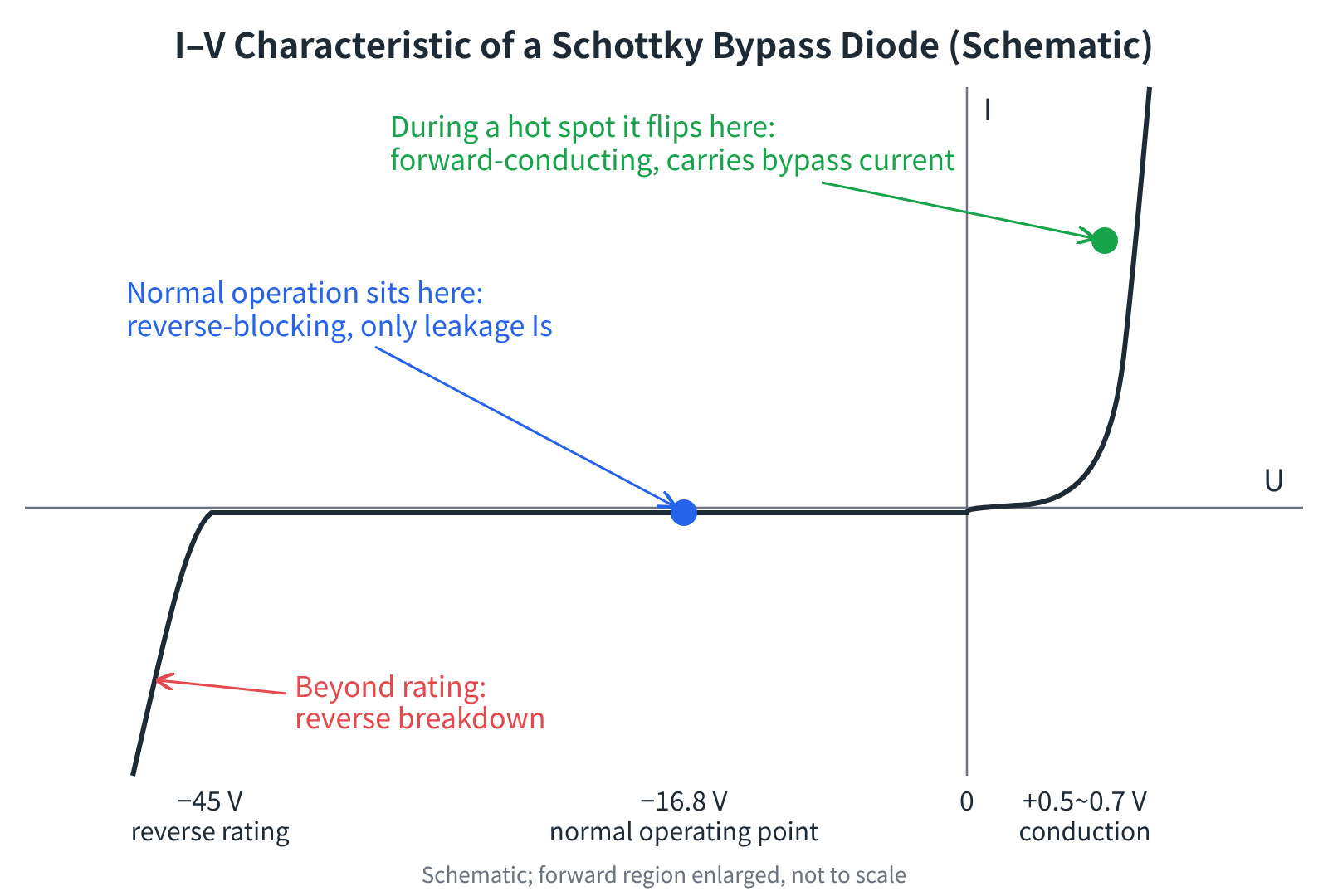
Figure 2 | The bypass diode's two operating points: normally parked in the reverse-blocking region, flipped into forward conduction when a hot spot occurs
2. What a cell becomes once it is shaded
To understand what changes under shading, we first need the cell's equivalent circuit.
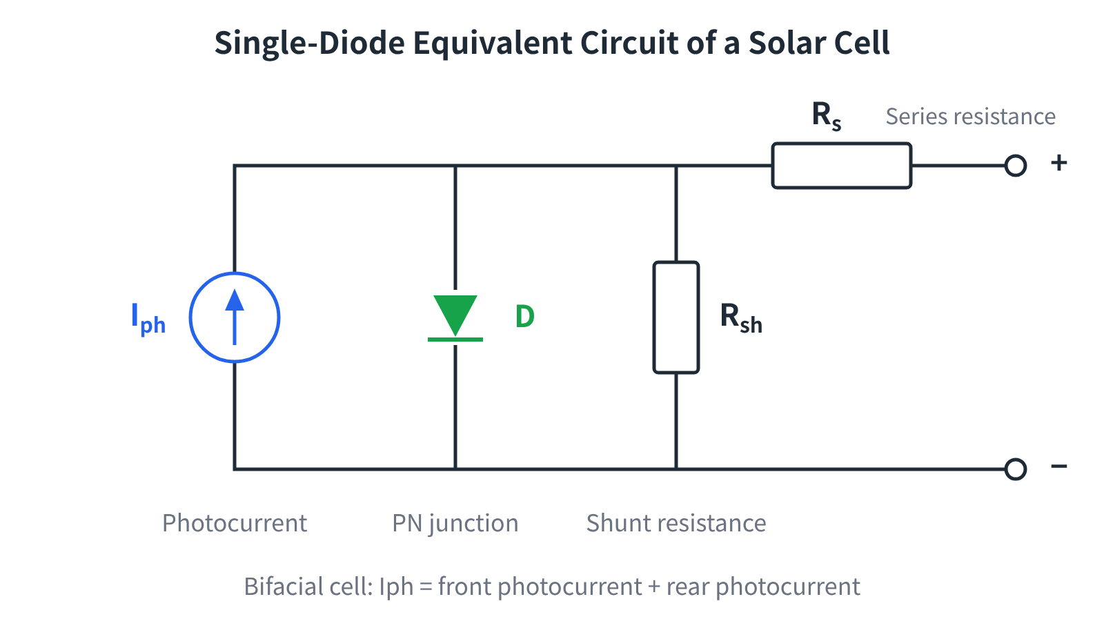
Figure 3 | Single-diode equivalent circuit of a solar cell (Single Diode Model)
A cell can be modelled with four elements:
| Element | Typical magnitude | Physical origin |
|---|---|---|
| Photocurrent source Iph | Proportional to irradiance | Light-generated carriers; for bifacial cells, the sum of front and rear photocurrent |
| Diode D | — | The cell's own PN junction |
| Shunt resistance Rsh | Hundreds to thousands of Ω | Junction defects, grain-boundary leakage, edge leakage, etc. |
| Series resistance Rs | 0.1 – 1 Ω | Finger contact resistance, bulk semiconductor resistance, ribbon resistance, etc. |
When a cell is shaded (or is already damaged), its photocurrent Iph falls towards 0 as the shaded area grows.
Once the current source "disappears," all that is left of the cell is a PN junction and two resistors, Rs and Rsh. It is no longer a source; it has become a load sitting in series in the circuit.
3. How the voltage drops, step by step
Here is the problem: this cell can no longer produce current, yet the other 23 cells in the same string are still generating, and their current has to pass through it.
In a series circuit the current is the same everywhere. For that current to flow "backwards" through the shaded cell's PN junction, which offers high resistance when reverse-biased, the other 23 cells must build up a large enough reverse voltage across it to force the current through.
So, as shading increases:
- The shaded cell's voltage falls from +0.7 V to 0 V, then on to −5 V, −10 V, −15 V…
- The total voltage of the 24-cell string falls along with it.
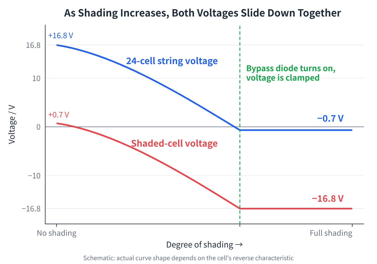
Figure 4 | As shading increases, the shaded-cell voltage and the string voltage fall together until the diode turns on
The critical moment comes when the shaded cell reaches −16.8 V. The string voltage is then:
−16.8 V + (23 × 0.7 V) = −16.8 V + 16.1 V = −0.7 V
A string voltage of −0.7 V is exactly a +0.7 V forward voltage for the anti-parallel bypass diode. PV Schottky diodes typically turn on at 0.5 – 0.7 V, so the conduction condition has been reached.
The diode turns on in the forward direction, and the main current reroutes through it.
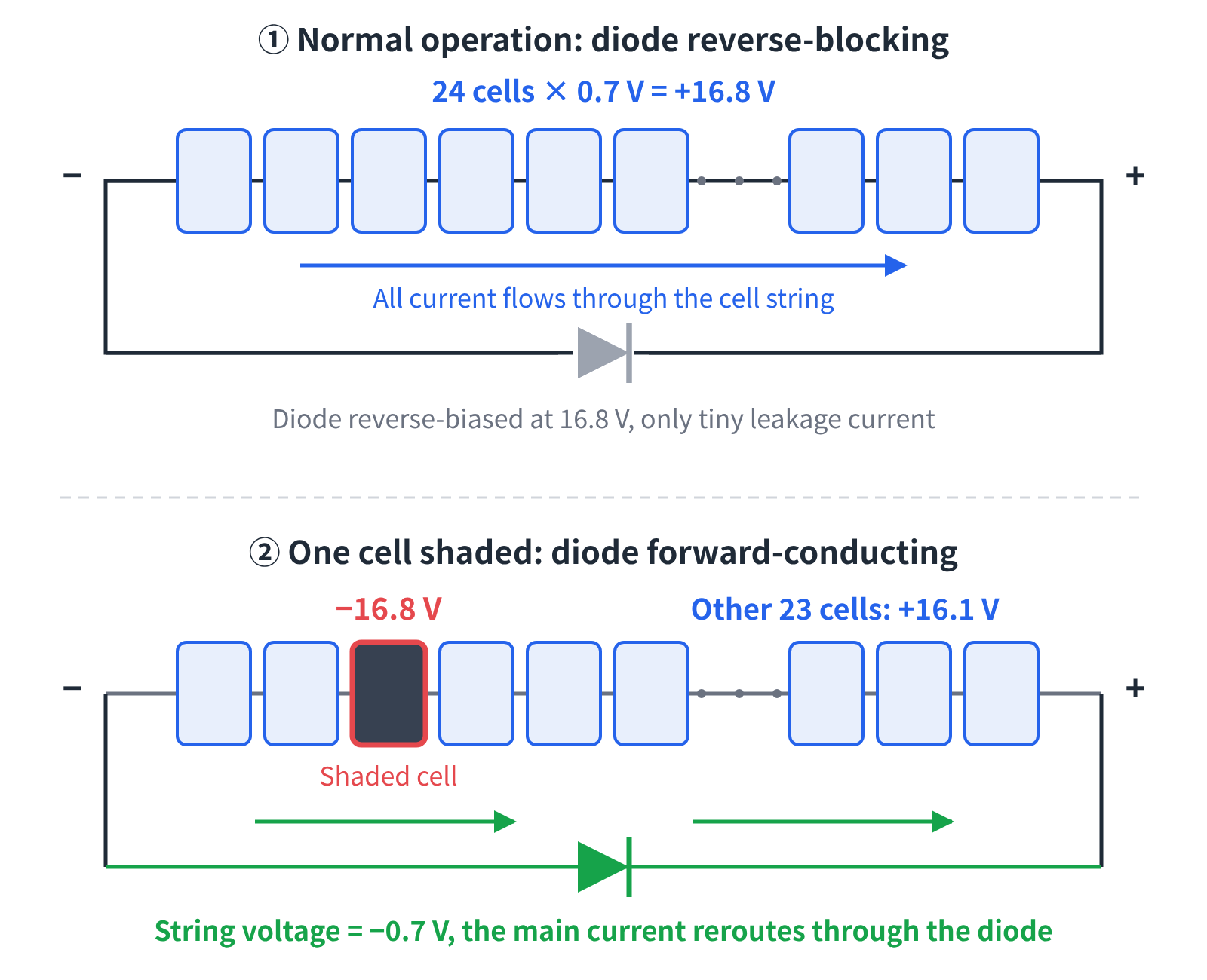
Figure 5 | Current paths before and after shading
The whole process in one table:
| Stage | Shaded-cell voltage | 24-cell string voltage | Bypass diode |
|---|---|---|---|
| No shading | +0.7 V | +16.8 V | Reverse-biased at 16.8 V, off |
| Shading increases | 0 → −5 → −10 → −15 V | Falling | Reverse bias shrinking, still off |
| Critical point | −16.8 V | −0.7 V | Forward-biased at 0.7 V, on |
| After turn-on | Clamped at about −16.8 V | About −0.7 V | Carries the bypass current |
This gives a very practical rule of thumb:
Maximum reverse voltage on the shaded cell ≈ (number of series cells under one diode − 1) × cell voltage + diode forward drop
The more cells a single diode watches over, the higher the reverse voltage the shaded cell has to withstand.
4. Once the diode turns on, is the hot spot gone?
No. The bypass diode limits the hot spot; it does not eliminate it.
After turn-on, the shaded cell is still clamped at a reverse voltage of about −16.8 V, and as long as any current flows through it, it heats up:
P = U × I
Under full shading, the current through it is mainly leakage current. Assuming an equivalent resistance of 20 – 50 Ω for the shaded cell:
- Current: 16.8 V ÷ (20 – 50 Ω) ≈ 0.3 – 0.8 A
- Power: 16.8² ÷ (20 – 50 Ω) ≈ 5.6 – 14 W
Ten watts or so spread evenly over a whole cell is not a big deal. But leakage tends to concentrate at defects, cell edges and other local spots, so the heat is concentrated in a very small area and the local temperature rises sharply.
Partial shading deserves even more attention. When only part of a cell is covered, it still has a substantial photocurrent while also sitting under a reverse voltage close to 16.8 V. High voltage plus high current means the dissipated power can be far higher than under full shading. This is why the IEC 61215 hot-spot endurance test (MQT 09) first identifies the "worst-case shading ratio" before running the test.
Two more points are worth noting:
- The energy loss is far more than one cell. Once the diode turns on, both the upper and lower strings it is connected across (48 cells, one-third of the module) are bypassed and no longer deliver power.
- The diode heats up too. In conduction it carries well over ten amperes; at a drop of about 0.5 V that is a continuous dissipation of several watts up to around ten watts, all of it inside the junction box. Junction-box thermal design and the bypass diode thermal test (MQT 18) exist precisely for this reason.
5. Why the cell's reverse breakdown voltage matters
The analysis above rests on one assumption: the shaded cell is not driven into reverse breakdown at −16.8 V.
Reverse breakdown voltages differ widely between cell technologies. Measurements published in 2026 by Fraunhofer CSP and co-authors put the breakdown onset of n-type TOPCon cells at about −39 to −49 V, HJT at about −30 V and PERC at about −22 to −24 V, all above the 16.8 V clamping voltage. BC (IBC) cells, by contrast, break down at only about −4.5 V.
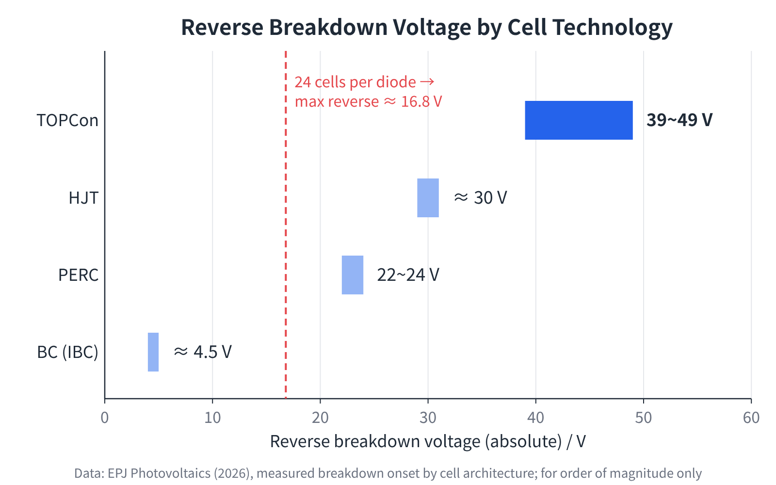
Figure 6 | Reverse breakdown voltage of different cell technologies compared with the 16.8 V clamping voltage (measured values from the literature, for order of magnitude only)
Three implications follow:
- For TOPCon modules with 24 cells per diode, the shaded cell never enters the breakdown region, and the current through it is set mainly by its shunt resistance and local leakage paths. The cell's leakage level (Rsh) and defect control therefore directly determine the hot-spot temperature.
- Conversely, a high breakdown voltage also means the shaded cell genuinely has to sustain close to 17 V of reverse bias. If the diode fails open, that reverse voltage is no longer clamped and the consequences can be far more serious.
- BC cells are a different case. They break down and conduct as soon as the reverse voltage reaches about 4.5 V, so the shaded cell's reverse voltage stays very low; in effect the cell "relieves the pressure" itself. The string voltage is then still about −4.5 V + 16.1 V ≈ +11.6 V, so with one fully shaded cell the bypass diode does not turn on at all. The study cited above concludes that, because the breakdown voltage is so low and the power available is limited, this does not cause significant heating. Still, the hot-spot mechanism differs from the other cell types, and BC modules need to be assessed on their own terms.
Summary
- In normal operation, the bypass diode sits under about 16.8 V of reverse bias, is switched off and carries only a tiny leakage current.
- When a cell is shaded, its photocurrent falls towards 0 and it turns from a "source" into a "load"; the other 23 cells build up a reverse voltage across it.
- When the shaded cell's reverse voltage reaches about −16.8 V, the string voltage becomes −0.7 V, the bypass diode turns on and the current reroutes.
- The diode only limits the reverse voltage and the heating power; the shaded cell keeps heating, and partial shading is often more dangerous than full shading.
- Together, the cell's leakage level and reverse breakdown behaviour, the diode's reliability and the number of cells per diode determine how severe a hot spot will be.
References
- IEC 61215-2: Terrestrial photovoltaic (PV) modules – Design qualification and type approval – Part 2: Test procedures (MQT 09 hot-spot endurance test, MQT 18 bypass diode testing)
- B. Jaeckel, J. Froebel, M. Pander, A. Maixner, H. Hanifi. Characterization and analysis of reverse breakdown voltage onset of solar cells with different cell architectures. EPJ Photovoltaics, 17, 4 (2026). DOI: 10.1051/epjpv/2025024
This article is a technical explainer; the figures in it are simplified estimates intended to aid understanding. Comments and corrections are welcome.