
Copper-Clad Aluminum (CCA) Ribbon: The Cost Is Tempting, So Why Are Leading PV Makers Still Holding Back?
The short answer
As of mid-2026, copper-clad aluminum (CCA) ribbon at tier-1 module makers is still mostly at the patent-filing, R&D-validation or small-pilot stage. The companies that have actually started small- to medium-volume use are mainly tier-2/3 and smaller module makers under heavier cost pressure.
The question is not "can it be made?" but "would you sign a 25-year warranty on it?" Electrochemical corrosion, thermal stress, the solder interface and the lack of long-term data are four hurdles, and none of them has been fully cleared yet.
01What is CCA ribbon?
Copper-clad aluminum (CCA) ribbon is a composite ribbon with an aluminium core and an outer copper cladding, made by drawing and reducing the wire, flattening it to shape and tin-plating it (referred to below as CCA ribbon).
The idea is simple: replace most of the copper with cheaper, lighter aluminium, keeping only the outer copper to ensure solderability and protect the aluminium core. With copper prices persistently high and module margins razor-thin, the appeal is obvious.
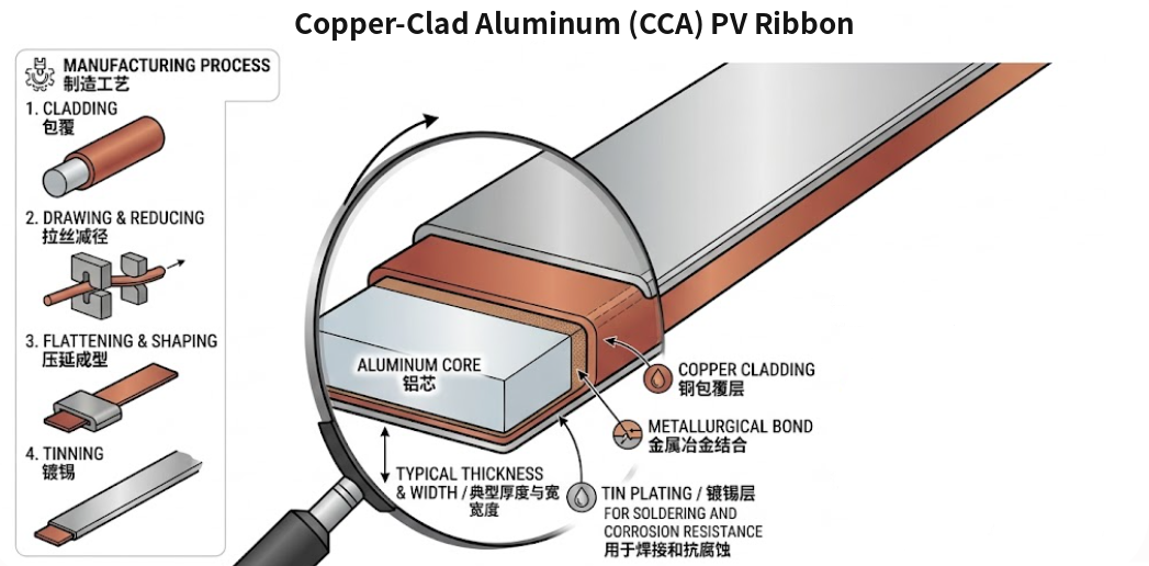
Figure 1 Structure and manufacturing process of copper-clad aluminum (CCA) PV ribbon (schematic)
02Current status: tier-1 cautious, tier-2/3 moving first
- Tier-1 makers: highly cautious. As of mid-2026, use of CCA ribbon at leading PV makers is still generally at the patent-filing, R&D-validation or small-pilot stage.
- Tier-2/3 and smaller makers: small- to medium-volume use has begun. At tier-2/3 module makers and some smaller makers of non-standard modules, CCA ribbon is already used in some products or for specific customer projects, for example modules for price-sensitive markets such as Africa, where quality requirements are relatively low.
In the end, this is driven by cost reduction.
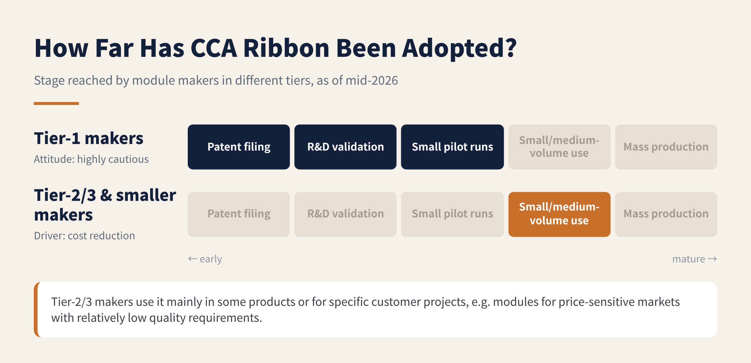
Figure 2 Adoption stage of CCA ribbon at module makers in different tiers
03Why haven't tier-1 makers adopted it at scale?
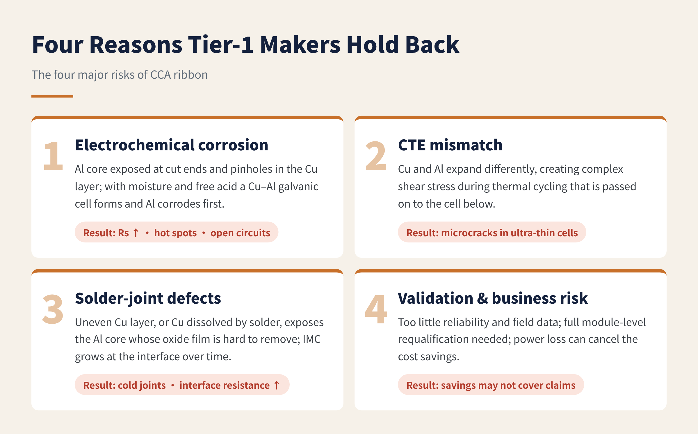
Figure 3 The four major risks of CCA ribbon
1. Electrochemical (galvanic) corrosion: the core risk, and the hardest to eliminate
This is the most fundamental risk of CCA ribbon and the hardest to eliminate. At the cut ends of the ribbon, or at pinholes in the copper layer caused by poorly controlled drawing, the aluminium core is directly exposed.
- Moisture is the catalyst. Although encapsulation materials and technology keep improving, moisture still inevitably seeps slowly into the module over 25 years of outdoor operation or long damp-heat tests (DH1000 / DH2000 / DH3000).
- Reaction mechanism. Once moisture gets in and combines with trace free acid that may be present in the encapsulant (such as acetic acid from EVA hydrolysis) or with ions from outside, it forms a microscopic "electrolyte pool" at the exposed copper–aluminium interface. Aluminium has a far lower electrode potential than copper, so aluminium becomes the anode and is oxidised and corroded first, while copper, as the cathode, is protected.
- Consequences. Corrosion steadily raises the local contact resistance and the module's series resistance (Rs). At best it causes extra power loss on top of PID and LID; at worst it creates local hot spots at the busbar or ribbon joints, and can even lead to burn-out or open circuits.
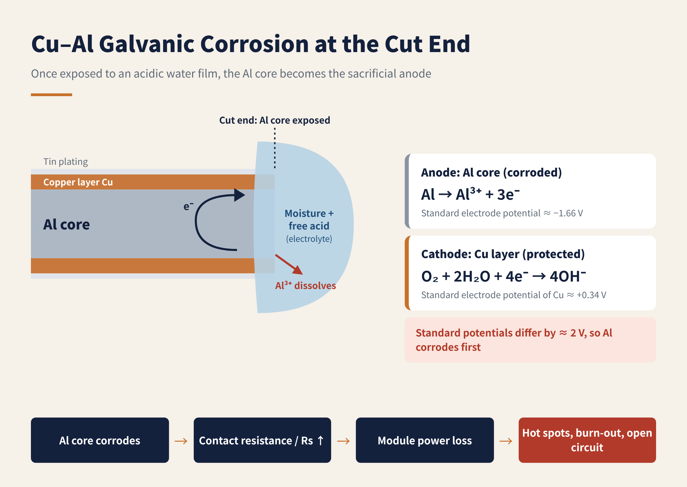
Figure 4 Cu–Al galvanic corrosion mechanism at the cut end
2. Thermal-expansion (CTE) mismatch: mechanical stress during thermal cycling
The coefficient of thermal expansion of aluminium is about 23.1×10⁻⁶/K, copper about 16.5×10⁻⁶/K, and silicon only about 2.6×10⁻⁶/K. When copper and aluminium are bonded together and go through sharp temperature swings, complex shear stresses develop inside the material.
- The thermal cycling (TC) challenge. In TC200, and in harsher TC400 / TC600 tests, the ribbon expands and contracts again and again. This stress tests not only the bond between the copper layer and the aluminium core but, more critically, transfers the cyclic internal stress directly to the cell underneath.
- A threat to thinner cells. Wafers for TOPCon and other high-efficiency n-type cells are now commonly 130 μm or thinner. The larger and more complex mechanical stress that CCA ribbon generates during temperature cycling can easily trigger microcracks in these ultra-thin cells.
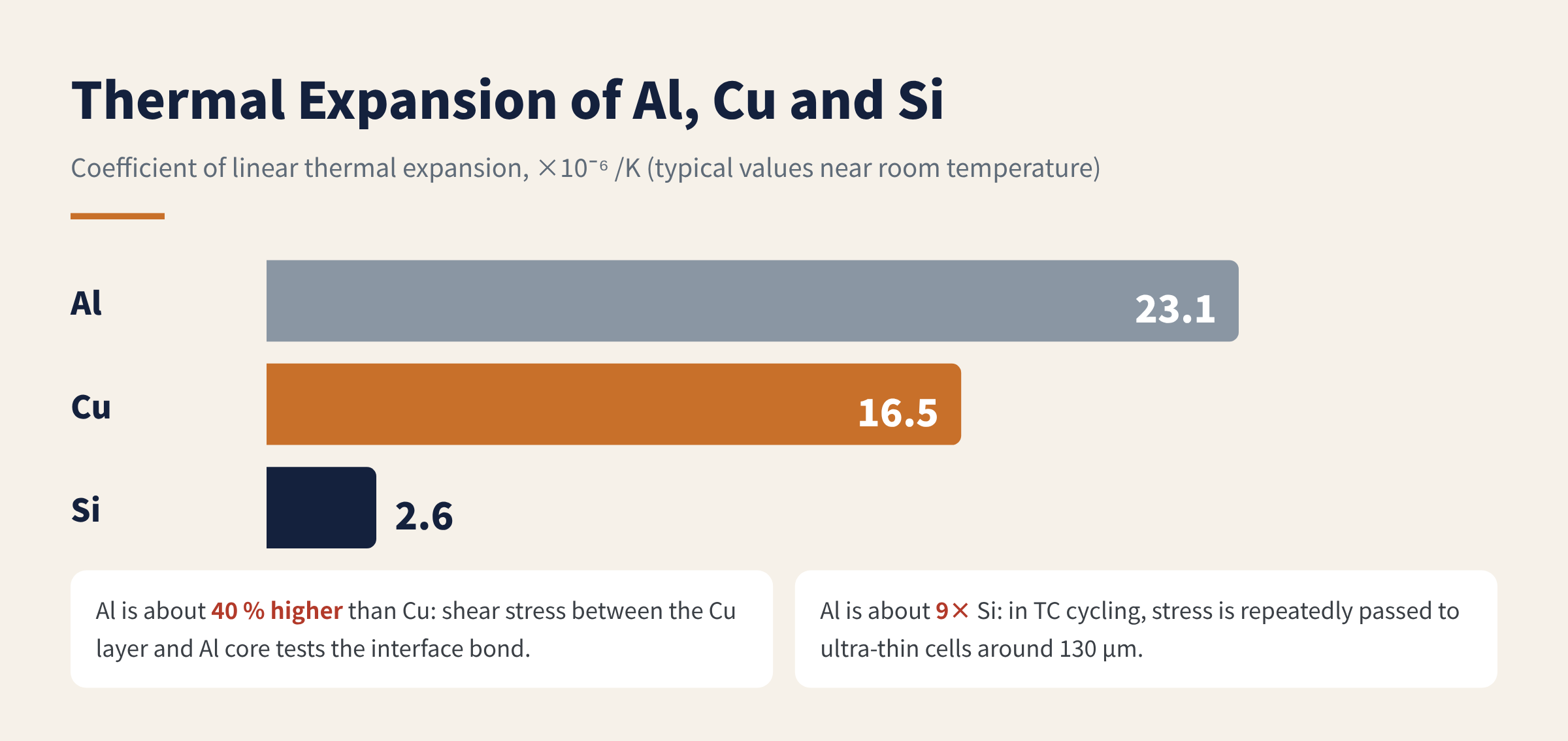
Figure 5 Thermal expansion coefficients of aluminium, copper and silicon
3. Solder interface: cold joints and excessive IMC growth
From the soldering side of module manufacturing, CCA ribbon also has built-in physical limitations.
- Wetting and cold joints. Aluminium readily forms a dense aluminium-oxide film. If the outer copper layer is uneven, or the copper dissolves into the solder at soldering temperature (especially with low-melting alloys containing bismuth or lead) so that the aluminium core is exposed, conventional PV fluxes struggle to remove that oxide film, and large-area cold joints are very likely.
- Interface resistance degradation. Even if the initial joint is good, over the long term the complex metal system of copper, aluminium, tin, silver and other trace alloying elements slowly forms brittle, poorly conducting intermetallic compounds (IMC) at the joint interface, pushing the module's series resistance up over time.
4. Long-term validation and business risk: the savings may not cover the claims
- Missing data. Pure copper ribbon has decades of mature data and extensive field feedback; reliability test data for CCA ribbon in PV, and outdoor data covering 25 years or more, are still clearly insufficient.
- Standards and certification. Existing module standards and certification practice have been built up around pure copper ribbon. Changing the ribbon base material is a critical material change, so manufacturers must spend significant extra time and money redoing full module-level qualification.
- Economic consequences. Even if material cost comes down, a power loss of just 0.1 %–0.5 %, or slightly lower reliability, is enough to wipe out the savings.
04One table: pure copper ribbon vs. CCA ribbon
| Dimension | Pure Cu ribbon (mainstream baseline) | CCA ribbon | Impact |
|---|---|---|---|
| Density | ≈ 8.9 g/cm³ | ≈ 3.3–4.2 g/cm³ (depends on Cu/Al ratio) | CCA is much lighter, giving more metres per kilogram |
| Volume resistivity | ≈ 1.68×10⁻⁸ Ω·m | ≈ 2.65×10⁻⁸ Ω·m (close to pure Al) | About 60 % higher; keeping the same series resistance requires a larger cross-section |
| Front-side optical shading | Smaller (diameters around 0.2 mm achievable) | Larger (thicker wire needed to make up for conductivity) | Thicker means more shading and less current; not thicker means higher resistance and lower FF; power is lost either way |
| Resistance to electrochemical corrosion | Excellent (single homogeneous metal) | Very poor (bimetallic galvanic reaction) | Ends and pinholes corrode easily; the core reason the mainstream market rejects CCA |
| Fine-wire drawing yield | Very high (easily drawn to 0BB diameters) | Lower (two metals deform together with difficulty) | Hard to keep up with the trend to ultra-fine SMBB and 0BB in n-type modules |
| Cost (ribbon cost per watt) | Higher (strongly affected by copper price) | Significantly lower (material cost down 20 %+) | Very attractive on initial purchase cost |
What does about 60 % higher resistivity mean in practice? A rough round-wire estimate: to match the resistance of a 0.20 mm pure copper ribbon, CCA ribbon needs about 60 % more cross-section, i.e. a diameter of about 0.25 mm.
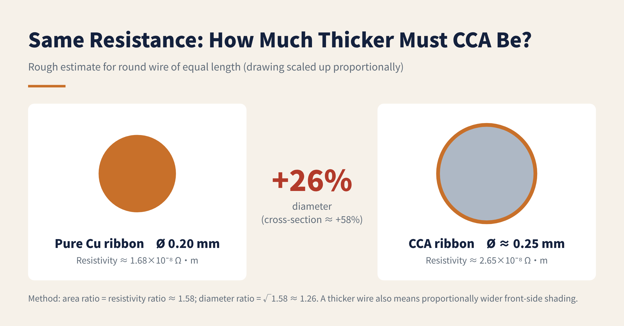
Figure 6 How much thicker CCA ribbon must be for the same resistance (estimated from the resistivities in the table)
Seen the other way round, even when thickened to the same resistance as copper, CCA ribbon weighs only about 60 %–75 % as much per metre as copper ribbon. That is why it always looks attractive on cost: the weight and cost savings are real; the price is paid in shading, processing and reliability.
05Final thoughts
The cost advantage is tempting, but reliability comes first.
This is why tier-1 makers are mostly still validating rather than introducing CCA at scale. For them, ribbon is a limited share of module cost, while a batch of field failures would put a 25-year warranty and the brand's reputation on the line. The arithmetic is not hard.
When could CCA ribbon really go mainstream? In our view, at least three questions need good answers first:
- How is the aluminium core protected at cut ends and at defects in the copper layer?
- Do power and resistance stay stable after extended damp-heat and thermal-cycling test sequences?
- Is there enough long-term outdoor field data to back it up?
Has your company or project worked with CCA ribbon? How did it perform in testing or in use? We would be glad to hear from you.
References
- IEC 61215-2:2021, Terrestrial photovoltaic (PV) modules – Design qualification and type approval – Part 2: Test procedures (MQT 11 thermal cycling, MQT 13 damp heat)
- ASTM B566, Standard Specification for Copper-Clad Aluminum Wire
- CRC Handbook of Chemistry and Physics: standard electrode potentials (Al³⁺/Al ≈ −1.66 V, Cu²⁺/Cu ≈ +0.34 V), typical resistivity and thermal expansion values
A PV R&D and technology team with 10+ years of experience | In-depth technical knowledge sharing
Materials · Reliability · Failure Analysis · Standards & Certification · Products · Processes
Exploring AI + PV; collaboration welcome
Disclaimer:
1. Original content reflects the authors' personal views only, is for reference only and does not constitute investment advice.
2. Reposted and cited content is credited to its source, out of respect for original work.
3. Some content was produced with AI assistance (chart generation, data retrieval, concept explanations, etc.); the core framework and key content were written by our technical team and reviewed by people.
4. If anything is inaccurate or infringes your rights, please leave a message or contact us and we will deal with it.