
PV PID Series #1: High Voltage Difference, the Entry Ticket to PID
PV PID Series · Part 1
Driven by a sustained high-voltage DC field, sodium ions (Na⁺) in PV glass migrate in one direction, pass through the encapsulant and damage the cell's microstructure. That is the PID most people know. And it all starts with a voltage difference.
01High voltage difference: the entry ticket to PID
PID (potential-induced degradation) is not a single phenomenon. By mechanism, it is usually split into three types:
| Type | Full name | In one line |
|---|---|---|
| PID-s | Shunting | Na⁺ penetrates the cell and creates leakage paths |
| PID-p | Polarization | Charge builds up in the passivation layer, raising surface recombination |
| PID-c | Corrosion | Electrochemical reactions corrode coatings or electrodes |
Their mechanisms and symptoms differ, and later articles will cover each. This one deals with a single point: every type of PID shares one precondition, a high voltage difference between the cells and the grounded frame.
Necessary: without a voltage difference there is no field to drive ion migration or charge build-up, so there is no PID.
Not sufficient: even with a voltage difference, PID only really happens when heat, humidity and the glass, encapsulant and cell themselves all "cooperate".
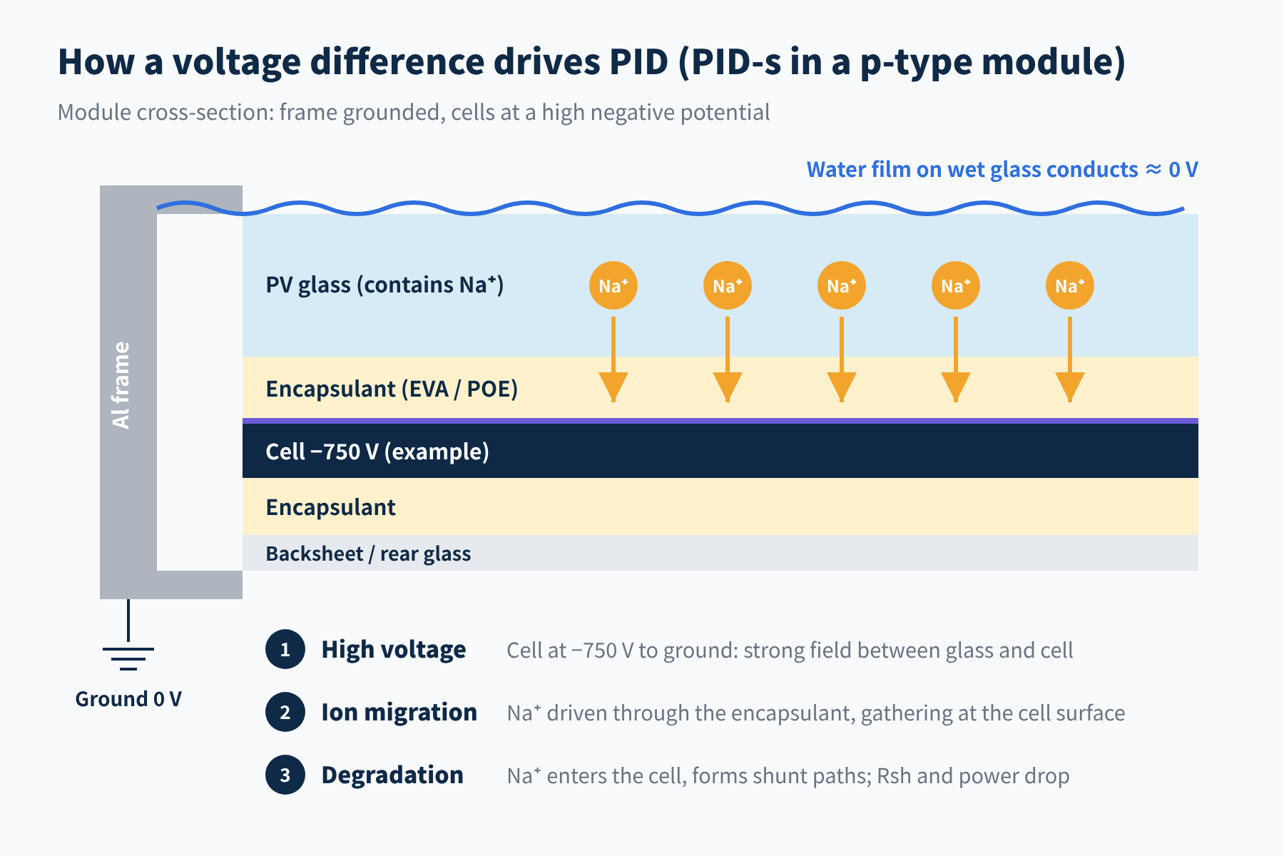
Figure 1 How a voltage difference drives PID (PID-s in a p-type module)
02Where does the voltage difference come from? Three grounding schemes
The module frame is grounded through the mounting structure, so it always sits at 0 V. A cell's potential to ground depends on where its module sits in the string and on how the plant's DC side is grounded.
One string of 30 modules at about 50 V each, so 1500 V for the string, numbered 1 to 30 from the positive end.
① Floating (ungrounded) system
Most of today's 1500 V plants use this scheme: with transformerless inverters, neither the positive nor the negative pole of the string is grounded directly. The potentials are usually distributed symmetrically, or nearly so, about ground, so the 1500 V is "shared" by both sides: about +750 V to ground at the positive end and about −750 V at the negative end.
| Module position | Positive terminal to ground | Negative terminal to ground |
|---|---|---|
| No. 1 (positive end) | +750 V | +700 V |
| No. 15 | +50 V | 0 V |
| No. 16 | 0 V | −50 V |
| No. 30 (negative end) | −700 V | −750 V |
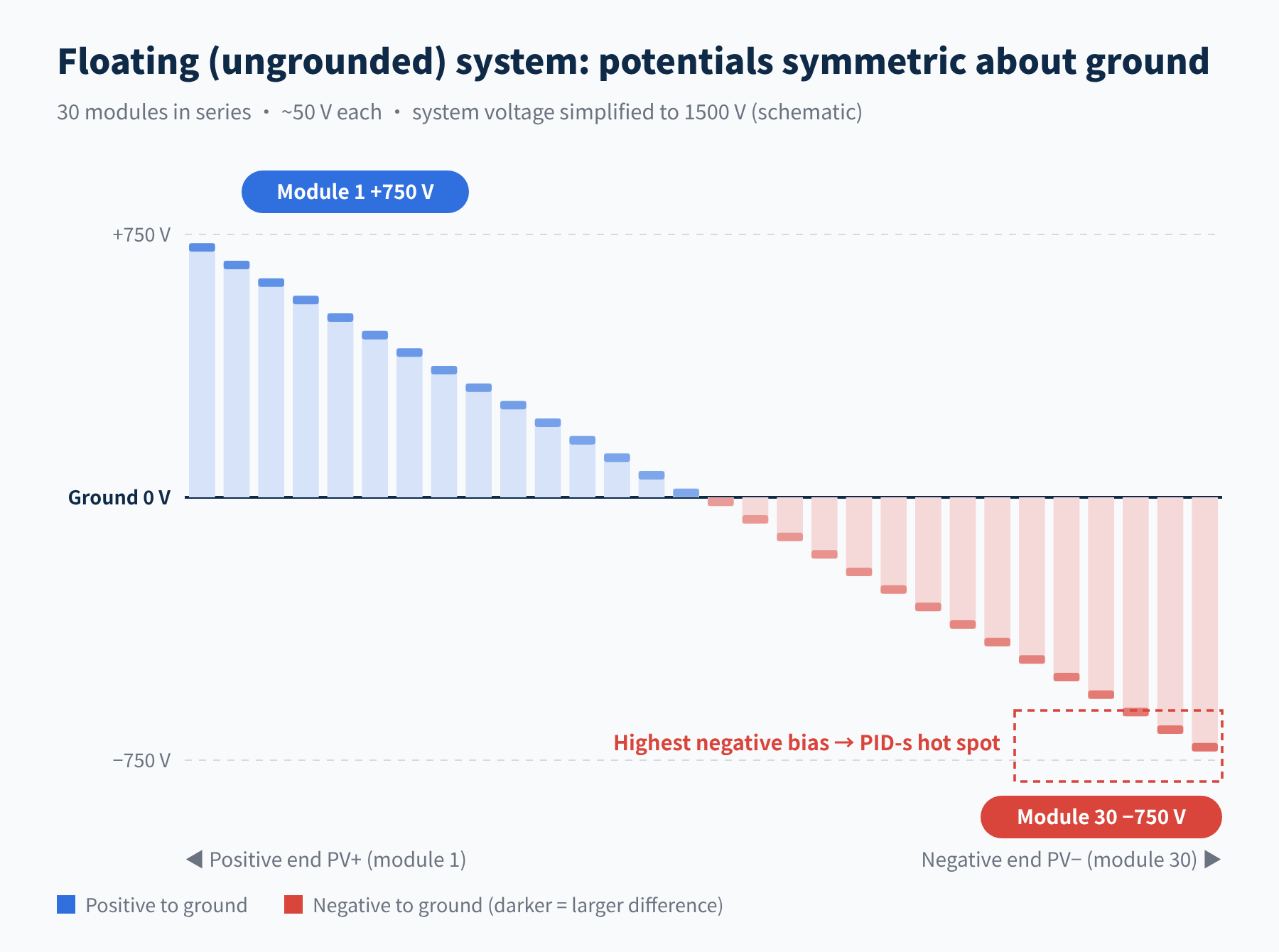
Figure 2 Floating system: string potentials symmetric about ground
In the modules near the negative end, the cells (about −750 V) and the grounded frame (0 V) are up to 750 V apart, in the negative direction. This is exactly where sodium-driven PID-s hits conventional p-type modules hardest.
② Negative-grounded system (active PID prevention)
Ground the negative pole of the string directly, and its most negative end is pinned at 0 V while the most positive end rises to +1500 V.
| Module position | Positive terminal to ground | Negative terminal to ground |
|---|---|---|
| No. 1 (positive end) | +1500 V | +1450 V |
| No. 15 | +800 V | +750 V |
| No. 30 (negative end) | +50 V | 0 V |
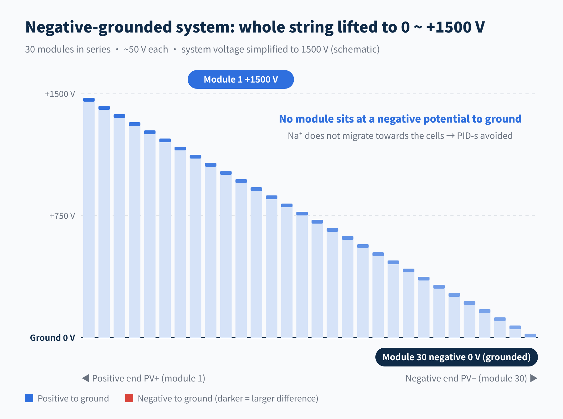
Figure 3 Negative-grounded system: the whole string is positive to ground
In this system no module sits at a negative potential to ground. With no negative field to "pull" them, Na⁺ ions in the glass no longer migrate towards the cells, and conventional PID-s is avoided.
③ Positive-grounded system (early, specific n-type modules)
This design is rare. It was mainly used with certain n-type cell structures, the classic case being early SunPower back-contact (IBC) modules: to suppress surface-polarization degradation on their front side, the manufacturer required the positive pole of the string to be grounded.
The most positive end is then at 0 V and the most negative end at −1500 V, so every module is negative to ground.
| Module position | Positive terminal to ground | Negative terminal to ground |
|---|---|---|
| No. 1 (positive end) | 0 V | −50 V |
| No. 15 | −700 V | −750 V |
| No. 30 (negative end) | −1450 V | −1500 V |
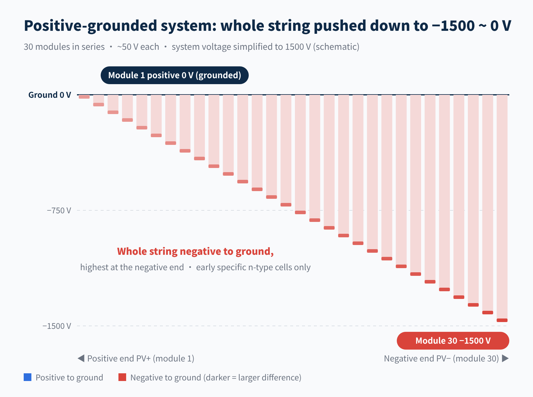
Figure 4 Positive-grounded system: the whole string is negative to ground
The three schemes at a glance
| Grounding | Potential range to ground | Max. negative bias | Typical use |
|---|---|---|---|
| Floating | −750 ~ +750 V | about −750 V | Today's mainstream 1500 V plants |
| Negative-grounded | 0 ~ +1500 V | none | Early p-type PID prevention |
| Positive-grounded | −1500 ~ 0 V | −1500 V | Early, specific n-type cells |
03If negative grounding prevents PID, why is it rarely used now?
For conventional p-type modules, negative grounding really is the right remedy. But it is leaving the mainstream, for four main reasons.
- Higher safety risk and harder O&M. With the negative pole grounded, the positive pole sits 1500 V above ground. If a cable on the positive side is damaged and touches ground, it closes a loop with the negative grounding point: in other words, a short circuit, with a fire risk. A floating system has no fixed grounding point, so a single fault or ground contact does not directly create a short-circuit loop, and the inverter's insulation-resistance monitoring raises an alarm in time. If a second ground fault appears, though, a loop still forms, so alarms should be investigated promptly.
- Inverters are now essentially transformerless. Early inverters had an internal isolation transformer, so the DC side was electrically isolated from the AC grid, and grounding the negative pole did not affect the grid. Today's string and central inverters generally use transformerless topologies (cheaper, smaller, more efficient), so the DC and AC sides are directly connected. Forcing the negative pole to ground on the DC side would create a fault loop through the grid's earthing point, leakage current would soar, and the inverter could not connect to the grid normally.
- Module technology has moved on, so the remedy no longer fits every case. P-type modules fear negative bias (it attracts Na⁺ and causes PID-s); negative grounding makes the whole string positive, so it "cures" them. For TOPCon and other n-type modules, however, PID is mainly polarization-type (PID-p): charge builds up in the passivation layer rather than Na⁺ creating shunts, and its sensitivity to bias polarity depends on the cell structure (front or rear side, monofacial or bifacial) and the encapsulant. NREL work published in 2024 found TOPCon PID-p mainly on the front side under negative bias; it was much milder under illumination but reached about 30% power loss in the dark. The rear passivation layer of a bifacial module can polarize too, so pushing the whole string to +1500 V does not guarantee that n-type modules are "immune". Negative grounding is no longer a universal cure.
- Cheaper alternatives exist. One on the inverter side and one on the materials side, described below.
Inverter side: virtual grounding plus night-time recovery. Many inverters have a built-in or optional anti-PID function, and stand-alone PID recovery boxes also exist. By day, "virtual grounding" lifts the string's potential so the negative pole is no longer negative to ground. At night, when the modules are not generating, a positive bias to ground is applied to push the Na⁺ that migrated during the day back out, like giving the modules a "therapy session" every night. Which method is used depends on the inverter maker, so check its documentation.
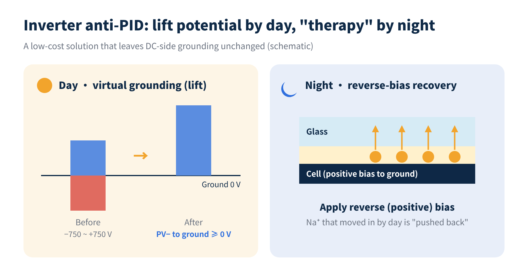
Figure 5 The two ways inverter anti-PID works
Materials side: cut the path at the source. A glass-glass construction with POE or EPE encapsulant, which has high volume resistivity and low water-vapour transmission, clearly weakens the ion-migration path and improves a module's PID resistance. Before shipment, modules must also pass the PID test in IEC 61215 (MQT 21, following the IEC TS 62804-1 method: system voltage applied for 96 hours at 85 °C / 85 %RH).
04Final thoughts
● A high voltage difference is a necessary, but not sufficient, condition for PID-s, PID-p and PID-c alike.
● Its size and polarity are set jointly by the module's position in the string and the system's grounding scheme.
● In mainstream floating systems, modules at the negative end see about −750 V to ground and are the high-risk zone for PID-s.
● Negative grounding is being phased out for reasons of safety, inverter topology and technology change; inverter anti-PID and materials solutions have become mainstream.
With the voltage-difference "ticket" in hand, what else does PID need before it actually happens? And how do the three types differ in mechanism? We will pick that up in the next article. This is Part 1 of our PV PID series; stay tuned, and we would be glad to hear from you.
References
- IEC TS 62804-1, Photovoltaic (PV) modules – Test methods for the detection of potential-induced degradation – Part 1: Crystalline silicon
- IEC 61215-2:2021, Terrestrial photovoltaic (PV) modules – Design qualification and type approval – Part 2: Test procedures (MQT 21, potential-induced degradation test)
- Kiwa PVEL, PV Module Reliability Scorecard – PID test method: scorecard.pvel.com/pid
- P. Hacke, S. Spataru, B. Habersberger, Y. Chen. Field-representative evaluation of PID-polarization in TOPCon PV modules by accelerated stress testing. Progress in Photovoltaics 32(5), 2024. NREL/JA-5K00-88644
A PV R&D and technology team with 10+ years of experience | In-depth technical knowledge sharing
Materials · Reliability · Failure Analysis · Standards & Certification · Products · Processes
Exploring AI + PV; collaboration welcome
Disclaimer:
1. Original content reflects the authors' personal views only, is for reference only and does not constitute investment advice.
2. Reposted and cited content is credited to its source, out of respect for original work.
3. Some content was produced with AI assistance (chart generation, data retrieval, concept explanations, etc.); the core framework and key content were written by our technical team and reviewed by people.
4. If anything is inaccurate or infringes your rights, please leave a message or contact us and we will deal with it.