
PV PID Series #2: PID-s, PID-p and PID-c, the Root Causes of Three Kinds of PID
PV PID Series · Part 2
In the last article we said a high voltage difference is PID's entry ticket. Yet with the same ticket, different cells walk through three different doors: some are "pierced" by sodium ions, some are "thrown off" by charge, and some are slowly "corroded". This article sets out the root cause of each.
01The big picture: three types of PID, three "illnesses"
PID-s, PID-p and PID-c differ by just one letter, but the physics behind them is completely different. Three analogies make them easy to remember:
| Type | Analogy | What it really is | Recoverable? |
|---|---|---|---|
| PID-s (shunting) | A "leaky" circuit | Na⁺ enters the Si and shorts the p-n junction | Mostly |
| PID-p (polarization) | A "statically charged" surface | Charge build-up, passivation fails | Essentially yes |
| PID-c (corrosion) | Material "rusting" | Electrochemical corrosion, structural damage | No |
Telling them apart matters because different root causes call for different remedies: what works on PID-s may not help with PID-p, and once PID-c has happened there is no undo.
02PID-s: sodium "pierces" the p-n junction
PID-s (shunting) was the first type to be recognized, and the one that gave plant owners the biggest headaches in the p-type era. The "sodium migration" in our previous article is exactly this.
What happens
When a p-type cell is negatively biased to ground, Na⁺ ions from the glass are driven by the field through the encapsulant and the SiNx anti-reflection coating, and gather at the silicon surface.
The key step happens inside the silicon: Na diffuses inwards along stacking faults (a type of planar defect) in the crystal, "decorating" defects that would normally not conduct and turning them into conductive paths. The n⁺ emitter on the front of a p-type cell is very shallow, only a few tenths of a micron, so these paths easily cross the p-n junction, like connecting countless tiny short circuits in parallel with it. This mechanism was confirmed by microscopic analysis at Fraunhofer CSP and other institutes.
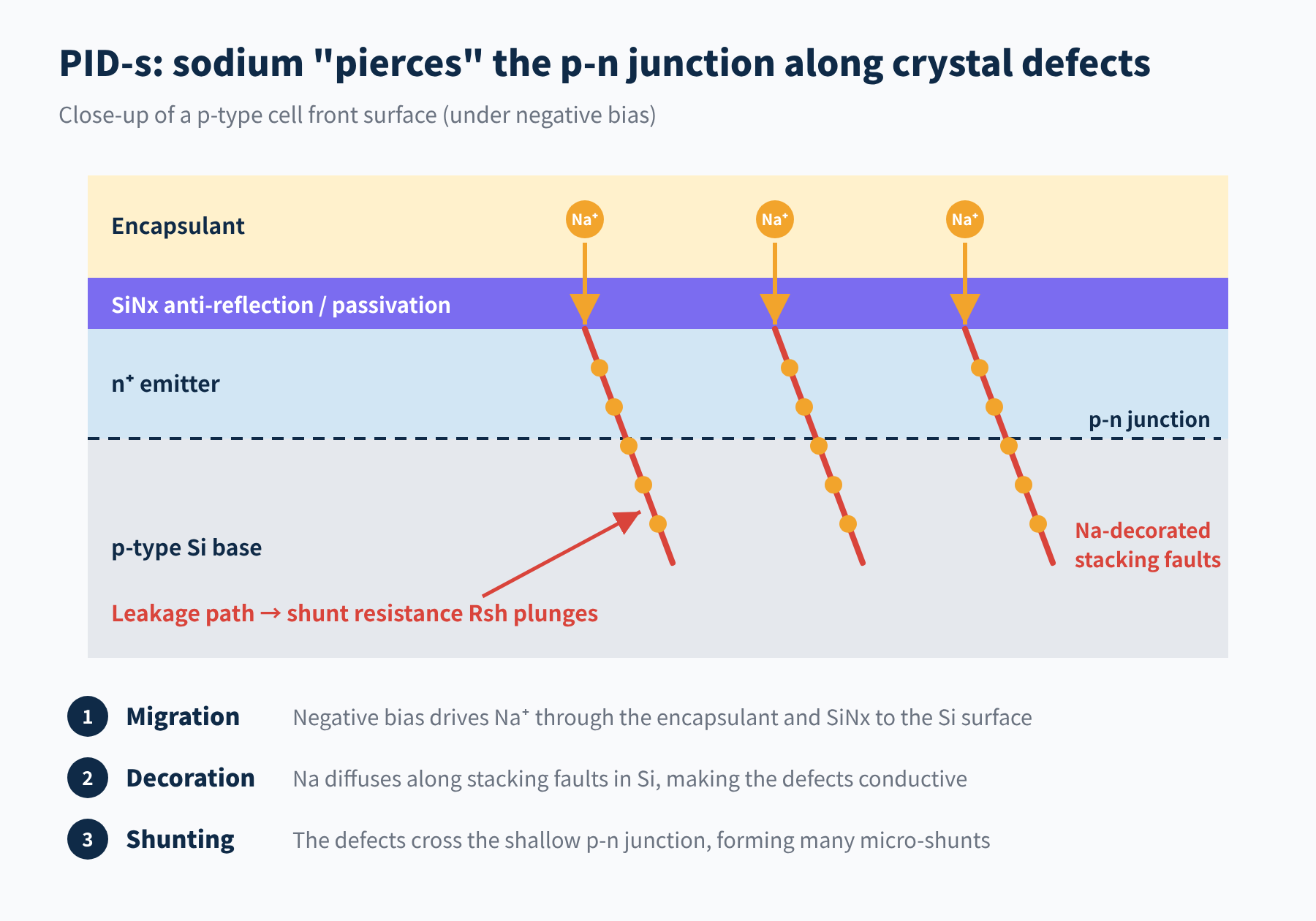
Figure 1 PID-s: Na-decorated stacking faults cross the p-n junction and form leakage paths
Symptoms
The most typical electrical signal is a sharp drop in shunt resistance Rsh: fill factor (FF) falls first, open-circuit voltage (Voc) follows, while short-circuit current (Isc) barely changes in the early stages. Because leakage weighs more heavily at low irradiance, power losses are especially obvious in weak light; yields that look "off" in the morning, evening or on cloudy days are often the first clue.
In EL images, affected cells go dark or completely black, usually starting with cells near the frame. Across a string, modules closer to the negative end are worse.
Can it recover?
Mostly, yes. Once the negative bias is removed, heating or applying reverse bias lets Na diffuse back out of the stacking faults and the leakage paths "heal". The night-time inverter recovery described in the previous article relies on exactly this. If the degradation is severe, though, recovery is often incomplete.
Who gets it: the front side of p-type cells (Al-BSF, PERC)
Polarity: cells negatively biased to ground
What to look at: Rsh↓, FF↓, clearly worse low-light performance
Reversibility: mostly reversible; severe cases leave a residue
03PID-p: the passivation layer is "thrown off" by charge
PID-p (polarization) is the lead actor in the era of high-efficiency cells. Its biggest difference from PID-s is that nothing "gets into" the silicon; what goes wrong is the passivation of the cell surface.
What happens
The surfaces of high-efficiency cells are covered with dielectric films such as AlOx and SiNx. Fixed charges in these films create an electric field at the silicon surface that "pushes" minority carriers away and reduces recombination. This is field-effect passivation.
Under a high voltage difference, foreign charge gradually builds up inside or on the surface of the dielectric. When its polarity is opposite to the fixed charge, field-effect passivation is cancelled or even reversed, minority carriers flood back to the surface, and surface recombination rises sharply.
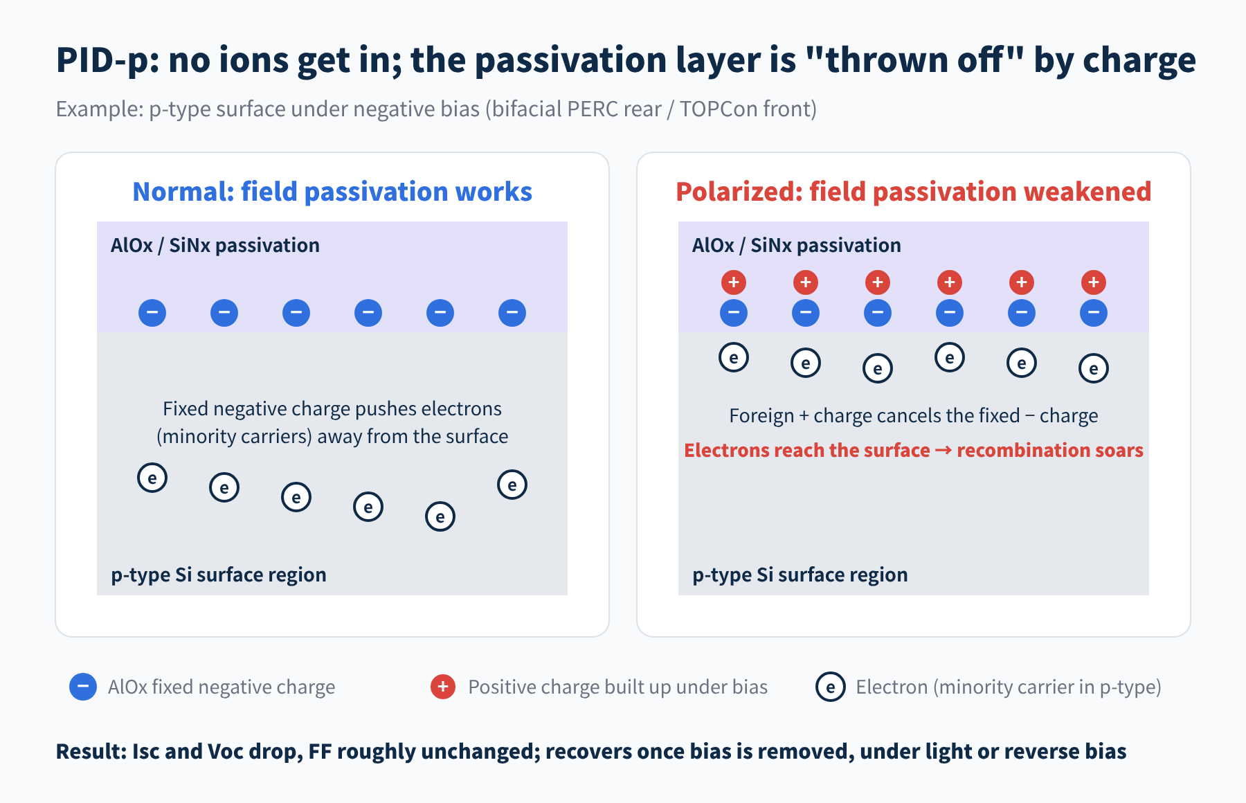
Figure 2 PID-p: built-up charge cancels the field-effect passivation
Three typical cases
- Early n-type back-contact (IBC) cells: this is where PID-p was first reported (around 2005, SunPower). With the module positively biased to ground, negative charge builds up on the front and pulls holes in the n-type silicon to the surface, where they recombine. The "positive grounding" in our last article was the remedy for it.
- The rear side of bifacial PERC: a bifacial cell no longer has a full-area aluminium layer on the rear, so the AlOx/SiNx passivation stack faces the encapsulant directly. Under negative bias, the positive charge that builds up cancels AlOx's fixed negative charge, and rear passivation deteriorates.
- The front side of TOPCon: TOPCon's front is a boron-diffused p⁺ emitter, also passivated by AlOx/SiNx. In published research, its PID-p appears mainly on the front under negative bias, while the heavily doped poly-Si layer on the rear is insensitive to surface charge and holds up well.
Symptoms
The opposite of PID-s: Isc and Voc drop while FF stays roughly the same, and shunt resistance shows no obvious change. EL images darken evenly overall rather than showing individual black cells. Another trait is speed: in accelerated tests it saturates within hours to days.
Can it recover?
Yes, and quickly. Removing the bias or applying reverse bias lets the built-up charge dissipate. Light works too, especially UV, which raises the conductivity of SiNx so the charge drains away more easily.
Because light suppresses PID-p, PID tests run in the dark often overstate real outdoor degradation. In one NREL test on TOPCon modules, power loss was about 30% in the dark, but only about 3% on average with roughly 0.1-sun UV light on the front. When reading a PID test report, the test conditions matter as much as the result.
Who gets it: bifacial PERC rear, TOPCon front, early IBC front
Polarity: depends on the surface doping type; positive or negative bias both possible
What to look at: Isc↓, Voc↓, FF roughly unchanged
Reversibility: essentially reversible; light and reverse bias speed up recovery
04PID-c: an irreversible "chemical injury"
PID-c (corrosion) is the quietest of the three, and the most troublesome.
What happens
Under the combined action of high voltage, moisture and ions, electrochemical reactions occur inside the module and the materials themselves corrode. In crystalline-silicon modules, the best-studied case is the rear of bifacial PERC: under negative bias, the silicon beneath the passivation stack is locally corroded and the passivation layer suffers structural damage.
In thin-film modules it shows up as corrosion and delamination of the transparent conductive oxide (TCO), which is where the term "corrosion-type PID" originally came from.
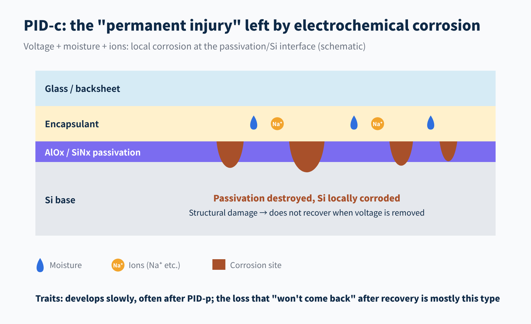
Figure 3 PID-c: local corrosion at the passivation/silicon interface (schematic)
Symptoms and reversibility
PID-c develops slowly and often follows PID-p: first comes reversible polarization, then, over time, irreversible corrosion is added on top. It causes structural damage, and neither removing the voltage, nor light, nor reverse bias can restore it.
There is a simple rule of thumb in practice: put a degraded module through a recovery treatment. Whatever comes back was PID-p or PID-s; whatever does not is most likely PID-c.
Who gets it: bifacial PERC rear, thin-film modules (TCO)
Conditions: high voltage plus moisture ingress, over a long time
What to look at: power loss that remains after a recovery treatment
Reversibility: irreversible
05Faced with a degraded module, how do you tell which it is?
In a real plant, all three types can occur together. A three-step check works well: position, curve, recovery.
Step 1: look at position
PID severity rises with voltage to ground. If degraded modules cluster at one end of a string while the other end is basically fine, suspect PID before other degradation mechanisms.
Step 2: look at the I-V curve
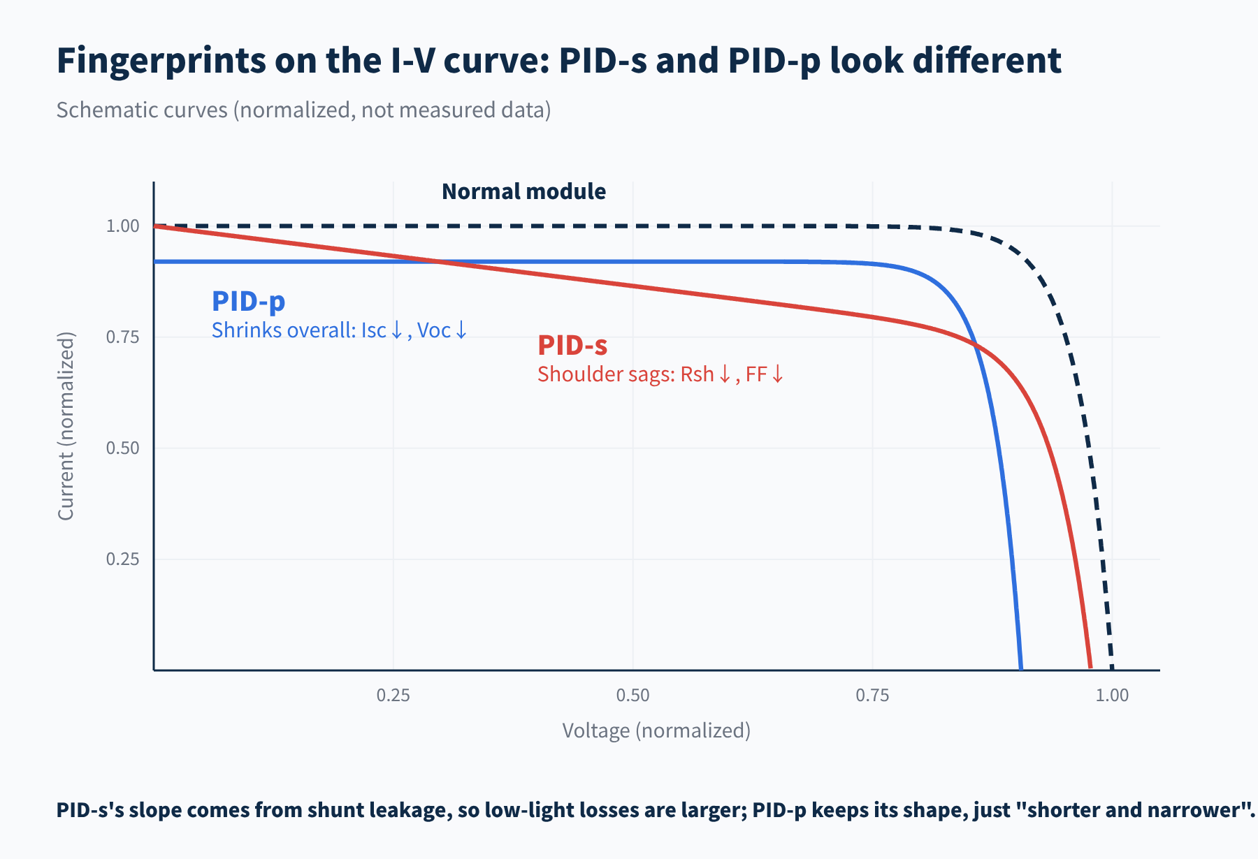
Figure 4 Different I-V "fingerprints" of PID-s and PID-p (schematic)
| Indicator | PID-s | PID-p |
|---|---|---|
| Isc | Barely changes early on | Drops |
| Voc | Drops | Drops |
| FF | Drops clearly | Roughly unchanged |
| Shunt resistance | Drops sharply | Roughly unchanged |
| Low-light performance | Clearly worse | Relatively little change |
| EL image | Individual black cells | Even darkening overall |
Step 3: run a recovery test
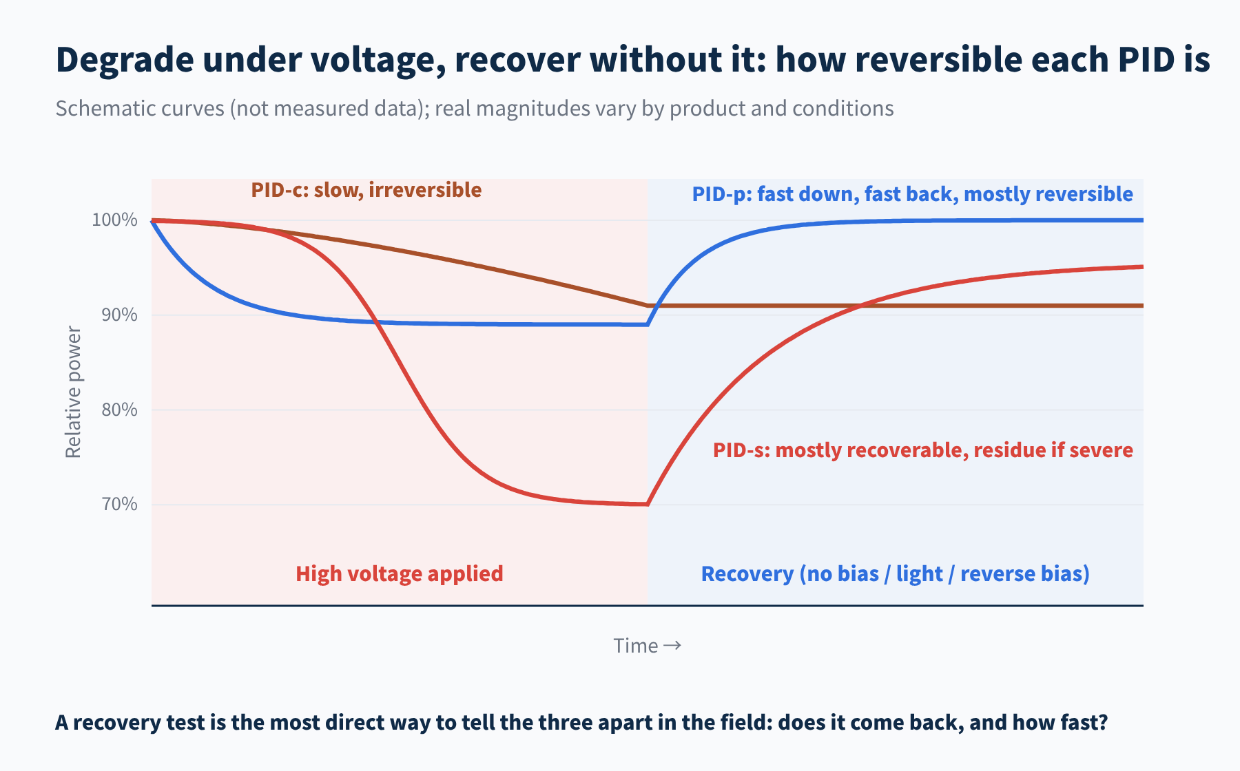
Figure 5 Degradation and recovery of the three PID types compared (schematic)
Take the module down, leave it under light or apply reverse bias, then measure power again: if it recovers quickly, it was PID-p; if it takes longer and recovers most of the way, PID-s; if it never comes back, PID-c.
Susceptibility by cell technology
| Cell technology | Main type | Sensitive side | Sensitive polarity |
|---|---|---|---|
| p-type Al-BSF / monofacial PERC | PID-s | Front | Negative bias |
| p-type bifacial PERC | PID-s + PID-p / PID-c | Front + rear | Negative bias |
| n-type TOPCon | Mainly PID-p | Front | Mainly negative bias |
| Early n-type IBC | PID-p | Front | Positive bias |
| Thin-film modules | PID-c | TCO layer | Negative bias |
The table shows typical cases from the published literature. Within one technology route, film-stack designs and encapsulants vary a lot between manufacturers, so measured results for the specific product are what count.
06Final thoughts
● PID-s is leakage caused by Na⁺ crossing the p-n junction along crystal defects; it costs FF and low-light performance, and is mostly recoverable.
● PID-p is passivation failure caused by charge build-up; it costs Isc and Voc, comes fast and goes fast.
● PID-c is structural damage from electrochemical corrosion; it develops slowly but is irreversible.
● To tell them apart, check position, check the I-V curve, and run a recovery test.
The voltage difference is the ticket; the mechanism is the root cause. So with the same voltage and the same cells, why do some modules stay healthy for ten years while others run into trouble in two or three? Next time we will look at the other half of what decides whether PID happens: temperature, humidity, and the glass and encapsulant. This is Part 2 of our PV PID series; stay tuned, and we would be glad to hear from you.
References
- R. M. Swanson, et al. The surface polarization effect in high-efficiency silicon solar cells. 15th PVSEC, Shanghai, 2005
- V. Naumann, et al. Explanation of potential-induced degradation of the shunting type by Na decoration of stacking faults in Si solar cells. Solar Energy Materials & Solar Cells 120, 383–389 (2014)
- K. Sporleder, doctoral thesis on PID (polarization and corrosion) of bifacial PERC cells, Martin Luther University Halle-Wittenberg, 2022: opendata.uni-halle.de; pv magazine: Behind PID in bifacial solar cells
- P. Hacke, S. Spataru, B. Habersberger, Y. Chen. Field-representative evaluation of PID-polarization in TOPCon PV modules by accelerated stress testing. Progress in Photovoltaics 32(5), 2024. NREL/JA-5K00-88644
- IEC TS 62804-1, Photovoltaic (PV) modules – Test methods for the detection of potential-induced degradation – Part 1: Crystalline silicon
A PV R&D and technology team with 10+ years of experience | In-depth technical knowledge sharing
Materials · Reliability · Failure Analysis · Standards & Certification · Products · Processes
Exploring AI + PV; collaboration welcome
Disclaimer:
1. Original content reflects the authors' personal views only, is for reference only and does not constitute investment advice.
2. Reposted and cited content is credited to its source, out of respect for original work.
3. Some content was produced with AI assistance (chart generation, data retrieval, concept explanations, etc.); the core framework and key content were written by our technical team and reviewed by people.
4. If anything is inaccurate or infringes your rights, please leave a message or contact us and we will deal with it.