
PV PID Series #3: Temperature, Humidity, Glass and Encapsulant, the Other Half of What Decides PID
PV PID Series · Part 3
Same 1500 V system, same position at the negative end: why do some modules stay healthy for ten years while others degrade noticeably within two or three? As Part 1 said, a high voltage difference is only a "necessary condition". This article fills in the other half: environment and materials.
01Meet an intermediate quantity: leakage current
A voltage difference does not harm a cell by itself. To turn into PID, it first has to drive a tiny current between the frame (ground) and the cells: the leakage current. The sodium migration and charge build-up covered in Parts 1 and 2 both ride on this current.
So the problem can be boiled down to one sentence: the larger the leakage current and the longer it flows, the faster PID arrives.
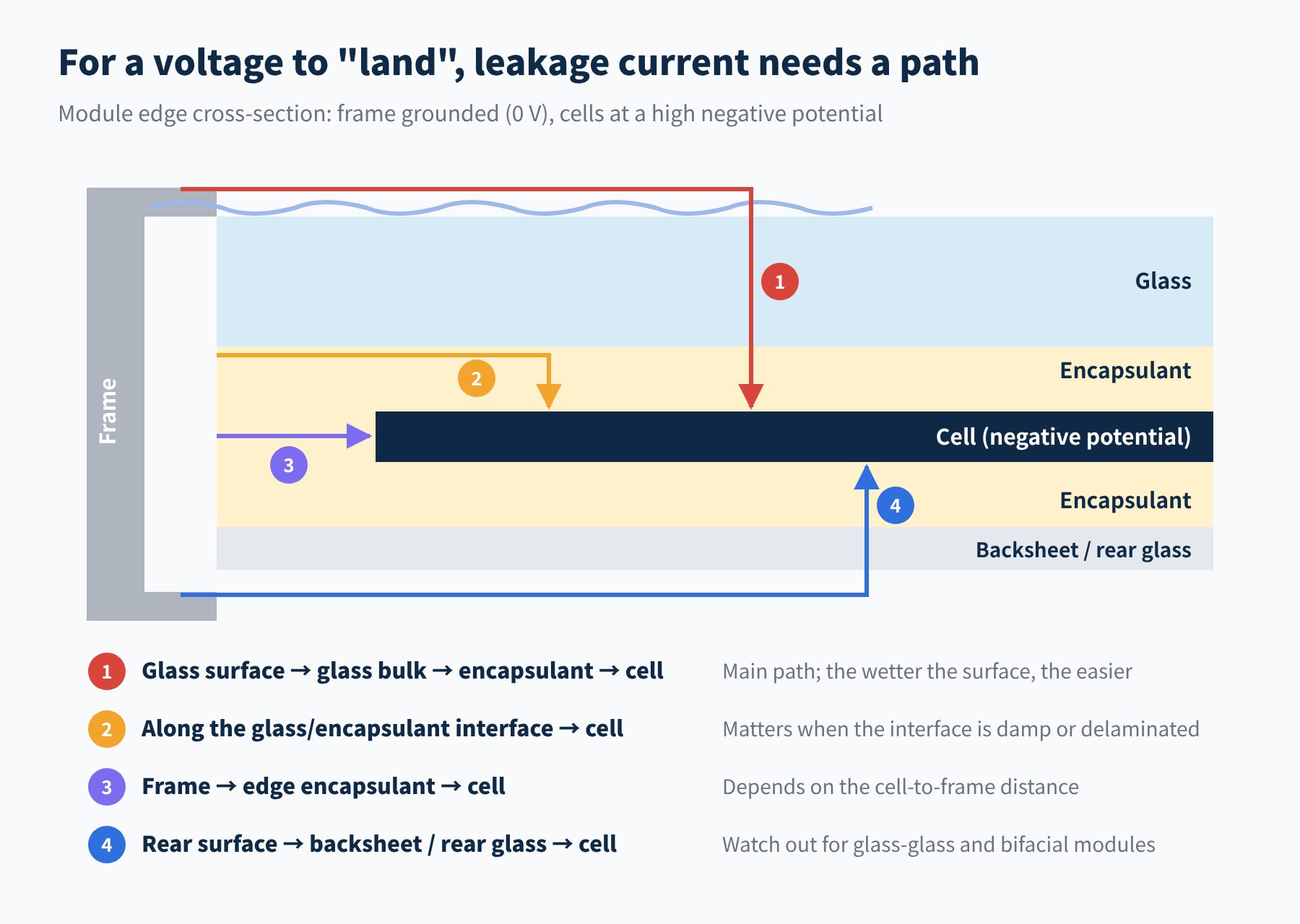
Figure 1 Four leakage-current paths between the frame and the cells (schematic)
Leakage current has several paths, and the most important is path 1: spreading across the glass surface, then passing through the glass and encapsulant to the cells. The reason is simple: the sodium ions behind PID-s come from the front glass.
Leakage current ≈ voltage difference ÷ loop resistance
The loop resistance is three segments in series: the glass surface, the glass bulk and the encapsulant. The environment mainly changes the resistance of the glass surface and the materials; the materials set the resistance of the glass bulk and the encapsulant. Every factor discussed below can be placed back into this expression.
02Environmental factors: temperature and humidity
Temperature: makes everything "run faster"
Glass and encapsulant are both insulators, but their resistivity falls exponentially as temperature rises, and ion migration through them speeds up accordingly. As a rule of thumb, every ten degrees or so of module temperature can double the leakage current.
At midday in summer, module operating temperature can be 20–30 °C above ambient. That is why PID develops faster in hot regions, and why accelerated tests are run hot: the common IEC TS 62804-1 condition is 60 °C / 85 %RH, while MQT 21 in IEC 61215 uses 85 °C / 85 %RH.
Humidity: turns the whole glass sheet into a "grounded electrode"
A dry glass surface has high resistance and only the frame is grounded, so the field concentrates on the ring of cells near the frame. That is why PID often starts at the module edge.
Once the glass is covered in dew or rain, or sits in high humidity, a conductive water film forms on the surface, and the whole glass surface comes close to 0 V. Every cell is then directly exposed to the full voltage difference.
Humidity has a second effect too: moisture slowly diffuses into the encapsulant and lowers its resistivity; in EVA, it also drives hydrolysis that produces acetic acid, further worsening insulation and the corrosive environment.
Together: two peaks in a day
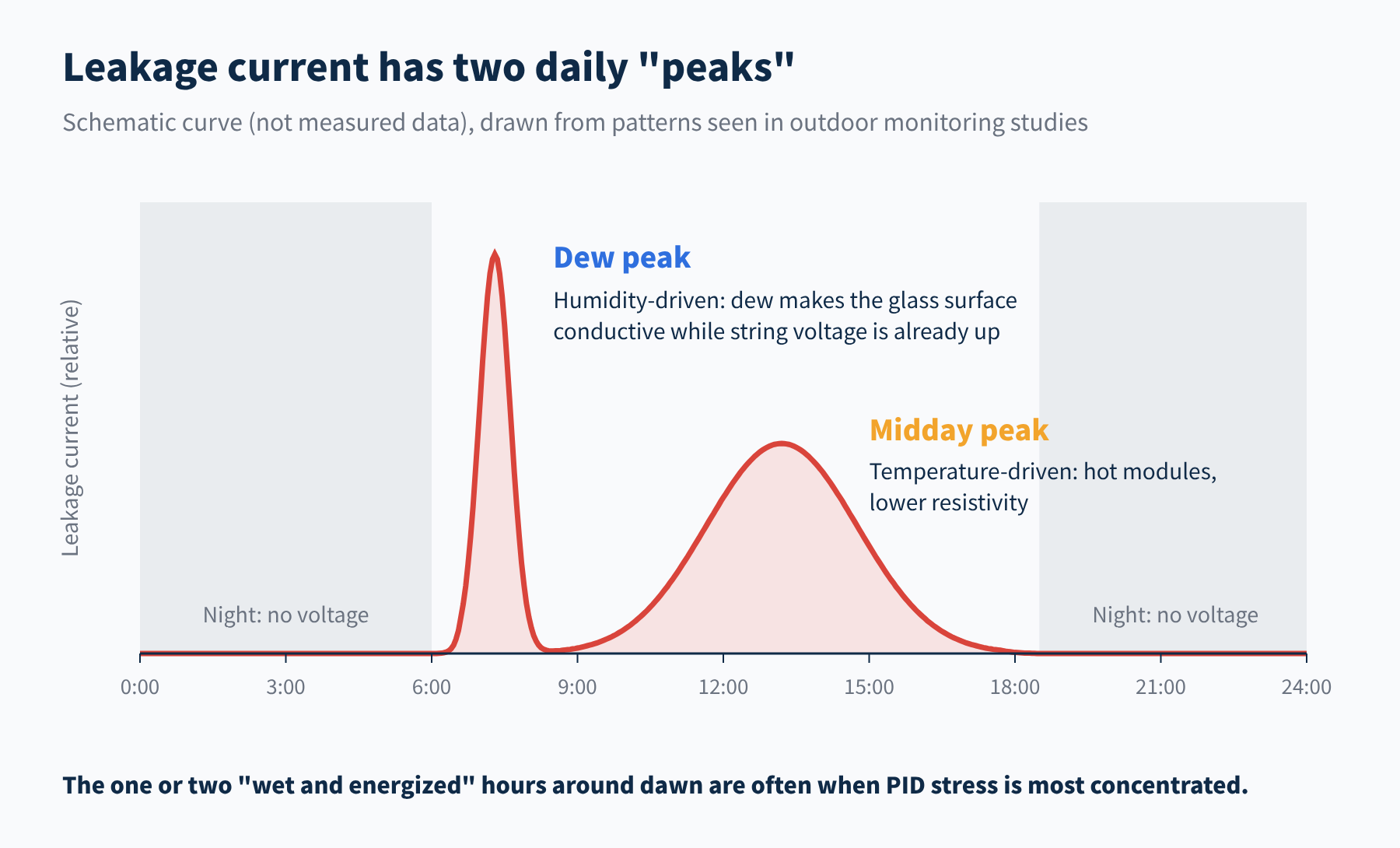
Figure 2 Daily pattern of outdoor module leakage current (schematic)
Outdoor monitoring studies have found two leakage-current peaks each day: an early-morning peak driven by dew and a broader midday peak driven by temperature. In the early morning, the modules are still wet with dew, yet string voltage is up as soon as the sun rises. "Wet and energized" is when stress is most concentrated during the day.
Scaling up to climate: where problems are most likely
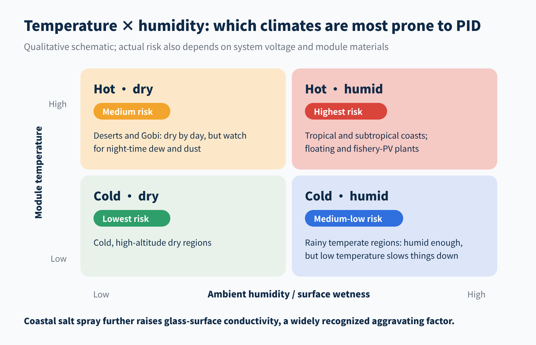
Figure 3 PID risk under different temperature and humidity combinations (qualitative)
Industry reviews of plants with PID have found that a large share sit in warm, coastal regions. On top of heat and humidity, coastal salt spray further raises glass-surface conductivity. Floating PV and fishery-PV projects, which have grown rapidly in recent years, also deserve close attention.
Dry regions are not off the hook either: places with large day–night temperature swings see frequent night-time dew, and dust on the module surface conducts once it absorbs moisture.
03Material factor 1: glass
PV glass is generally soda-lime glass, with a sodium-oxide content in the low teens of percent; it is the main source of the sodium ions in PID-s. Early studies ran a comparison: when the front glass was replaced with a sodium-free material (such as quartz glass), PID-s essentially disappeared.
The catch is that sodium-free or low-sodium specialty glass costs much more and is not practical for mass-produced modules. So the industry's mainstream approach is not to "change the glass" but to "block the path behind the glass", which is the encapsulant in the next section.
Glass-glass modules need extra attention. With glass on the rear as well, there is a second sodium source and an extra leakage path (path 4 in Figure 1), and the rear of a bifacial cell happens to lack a full-area aluminium layer for protection. That is the root of the bifacial-PERC rear-side PID-p and PID-c discussed in Part 2.
Frames and mounting also play a role: in frameless modules and clamp-mounted modules, the grounded metal touches the glass over a smaller area, so the "entrance" for leakage current is narrower too.
04Material factor 2: encapsulant
Sandwiched between the glass and the cells, the encapsulant is the most critical segment of the leakage loop. Its key metric is volume resistivity: the higher it is, the smaller the leakage current and the harder it is for ions to get through.
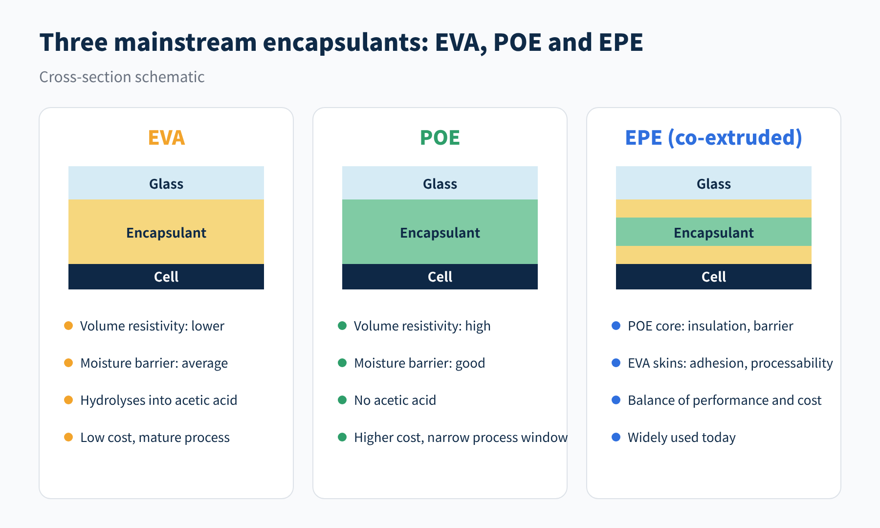
Figure 4 Three encapsulants compared: EVA, POE and EPE
| Metric | EVA | POE |
|---|---|---|
| Volume resistivity (room temp.) | Standard: ~10¹⁴ Ω·cm; anti-PID grades up to ~10¹⁵ | High, up to 10¹⁵–10¹⁶ Ω·cm |
| Water-vapour transmission | Higher | Low, a fraction of EVA's |
| Ageing by-products | Hydrolysis produces acetic acid | No acetic acid |
| Cost and process | Low cost, mature process | Higher cost, narrow lamination window |
The values are typical orders of magnitude; they vary markedly between suppliers and grades, so rely on the specific datasheet and measurements. Two points deserve emphasis:
- Not all EVA is equal. Volume resistivity can differ by an order of magnitude between suppliers; "anti-PID EVA" simply means a formulation engineered for higher resistivity. The word "EVA" alone tells you nothing about PID resistance.
- Resistivity is not a fixed number. It falls markedly with rising temperature and moisture uptake. An encapsulant that looks adequate at room temperature and dry may fall well short in damp heat. This is exactly where POE shines: high resistivity, low water uptake and no acetic acid, so it stays stable in heat and humidity. When selecting materials, also look at resistivity around 60 °C, not just the room-temperature figure.
EPE combines the two in a three-layer co-extruded film: the POE core provides insulation and a moisture barrier, while the EVA skins bond to the glass and cells and improve laminating behaviour. It is currently a widely used compromise between performance and cost. For glass-glass and n-type modules, which are more sensitive to PID, POE or EPE has become essentially standard.
05Material factor 3: the cell's own coatings
The last segment of the loop is the cell surface. When the same ions and charges reach the cell, whether the cell "takes the hit" depends on the design of its surface films.
- Against PID-s: the early approach was to raise the refractive index of the SiNx anti-reflection coating (making it more silicon-rich and more conductive, so charge does not pile up on it), at the cost of some optical loss. The more common approach later was to add a very thin, dense oxide layer between the SiNx and the silicon as a barrier. Research has also shown that emitter surface doping affects PID-s sensitivity, so it is not determined by refractive index alone.
- Against PID-p: the key is the design of the passivation stack, for example AlOx thickness, SiNx composition and stack structure. Processes differ a lot between manufacturers here, and this is the main reason why PID performance can vary so widely between TOPCon products.
The "anti-PID cells" on the market today are products that have been specifically optimized at this layer.
06Putting it together: three lines of defence
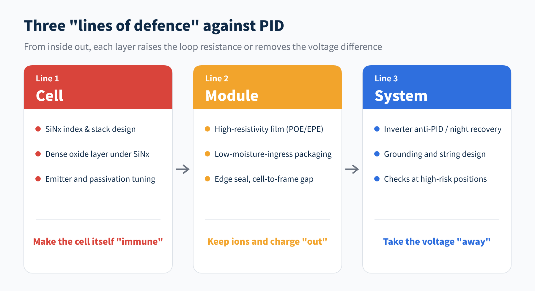
Figure 5 Anti-PID measures at cell, module and system level
The industry usually groups anti-PID measures into three levels: cell, module and system. The three lines of defence are not alternatives; they stack: the cell level lowers sensitivity, the module level cuts the path for ions and charge, and the system level removes the voltage difference or shortens the time it acts.
| Factor | What it affects | Higher PID risk when… |
|---|---|---|
| System voltage and polarity | Driving force | Voltage to ground is larger |
| Module temperature | Material resistivity, ion migration | Temperature is higher |
| Humidity / surface wetness | Glass-surface resistance | Wetter, more frequent dew |
| Glass | Sodium source, bulk resistance | Higher sodium, lower resistivity |
| Encapsulant | Loop resistance, moisture barrier | Lower resistivity, higher water permeability |
| Cell coatings | Intrinsic sensitivity | No anti-PID design |
07Final thoughts
● A voltage difference acts through leakage current; leakage current ≈ voltage difference ÷ loop resistance.
● Temperature lowers material resistivity and humidity makes the glass surface conductive; dewy early mornings and hot, humid coastal regions carry the highest risk.
● Glass is the sodium source and the encapsulant is the most critical "gate"; volume resistivity and moisture resistance are the key metrics.
● Beating PID takes the cell, module and system lines of defence stacked together, not any single measure.
That completes "why PID happens". The next question is more practical: how do you test whether a module resists PID, and how should you read a manufacturer's PID test report? Next time we will look at test methods and standards. This is Part 3 of our PV PID series; stay tuned, and we would be glad to hear from you.
References
- W. Luo, et al. Potential-induced degradation in photovoltaic modules: a critical review. Energy & Environmental Science 10, 43–68 (2017)
- S. Hoffmann, M. Koehl. Effect of humidity and temperature on the potential-induced degradation. Progress in Photovoltaics 22, 173–179 (2014)
- P. Hacke, et al. Accelerated testing and modeling of potential-induced degradation as a function of temperature and relative humidity. NREL: osti.gov/biblio/1250678
- S. Pingel, et al. Potential induced degradation of solar cells and panels. 35th IEEE PVSC, 2010
- IEC TS 62804-1, Photovoltaic (PV) modules – Test methods for the detection of potential-induced degradation – Part 1: Crystalline silicon; IEC 61215-2:2021 (MQT 21)
A PV R&D and technology team with 10+ years of experience | In-depth technical knowledge sharing
Materials · Reliability · Failure Analysis · Standards & Certification · Products · Processes
Exploring AI + PV; collaboration welcome
Disclaimer:
1. Original content reflects the authors' personal views only, is for reference only and does not constitute investment advice.
2. Reposted and cited content is credited to its source, out of respect for original work.
3. Some content was produced with AI assistance (chart generation, data retrieval, concept explanations, etc.); the core framework and key content were written by our technical team and reviewed by people.
4. If anything is inaccurate or infringes your rights, please leave a message or contact us and we will deal with it.