
How a Small MC4 Connector Has Stayed on Top in PV for Twenty Years
Key points
A connector has one job: holding its contact resistance steady for more than twenty years. The MC4 does this through four lines of defence (parallel multi-point contact, sealing, locking and materials). Add field data from billions of units and the "same maker, same type" rule, and it becomes the low-uncertainty choice for project owners.
On a module's bill of materials, the connector is probably the least noticeable item: two black plastic plugs that account for a tiny share of the cost. Yet in many overseas project specifications it gets a line of its own: Connector: Stäubli MC4 (original).
Wafers have grown from 156 mm to 210 mm, cells have moved from BSF to TOPCon and BC, and module power has multiplied several times. The connector that appeared around 2004, however, looks much the same as it always did. Here we look at why it has lasted twenty years, and why customers ask for it by name.
01What is the MC4?
MC stands for Multi-Contact, and 4 is the 4 mm pin diameter. Multi-Contact was a Swiss electrical connector company that launched the MC3 PV connector in 1996. In 2002 the Stäubli group took a majority stake; the MC4 followed, and in 2017 Multi-Contact was renamed Stäubli Electrical Connectors.
Compared with the MC3, the MC4 changed two things: the pin grew to 4 mm, and a snap-in locking latch was added. The 2008 edition of the US National Electrical Code (NEC) began requiring PV connectors that need a tool to open. The latching MC4 met that requirement and spread quickly from then on.
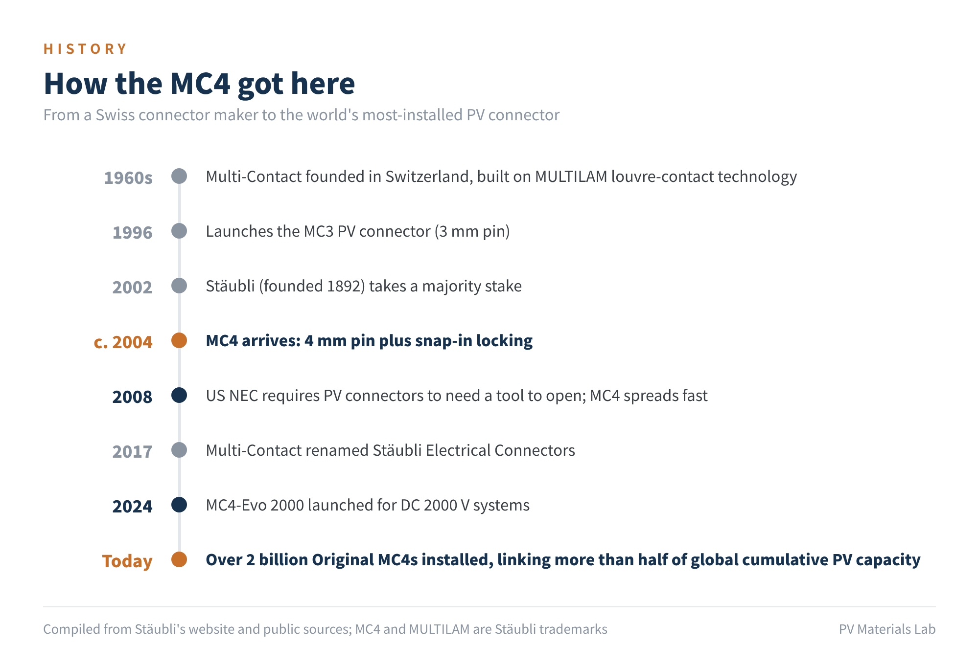
Figure 1 How the MC4 got here
According to Stäubli's website, more than 2 billion Original MC4 connectors have been installed, linking more than half of the world's cumulative PV capacity.
"MC4" is a Stäubli registered trademark for a specific product, not a generic name for a type of interface. "MC4-compatible" or "MC4-type" connectors are products from other makers with a similar shape. This distinction matters later on.
02A connector has one job: hold its contact resistance
Connectors fail in many ways, but most of them come down to the same thing: rising contact resistance.
Heat generated is P = I²R. At a string current of 15 A, a contact resistance of 0.2 mΩ produces about 0.045 W at a single connection, which is negligible. At 5 mΩ it is about 1.1 W; at 50 mΩ it is about 11 W, all concentrated in a contact zone the size of a fingernail.
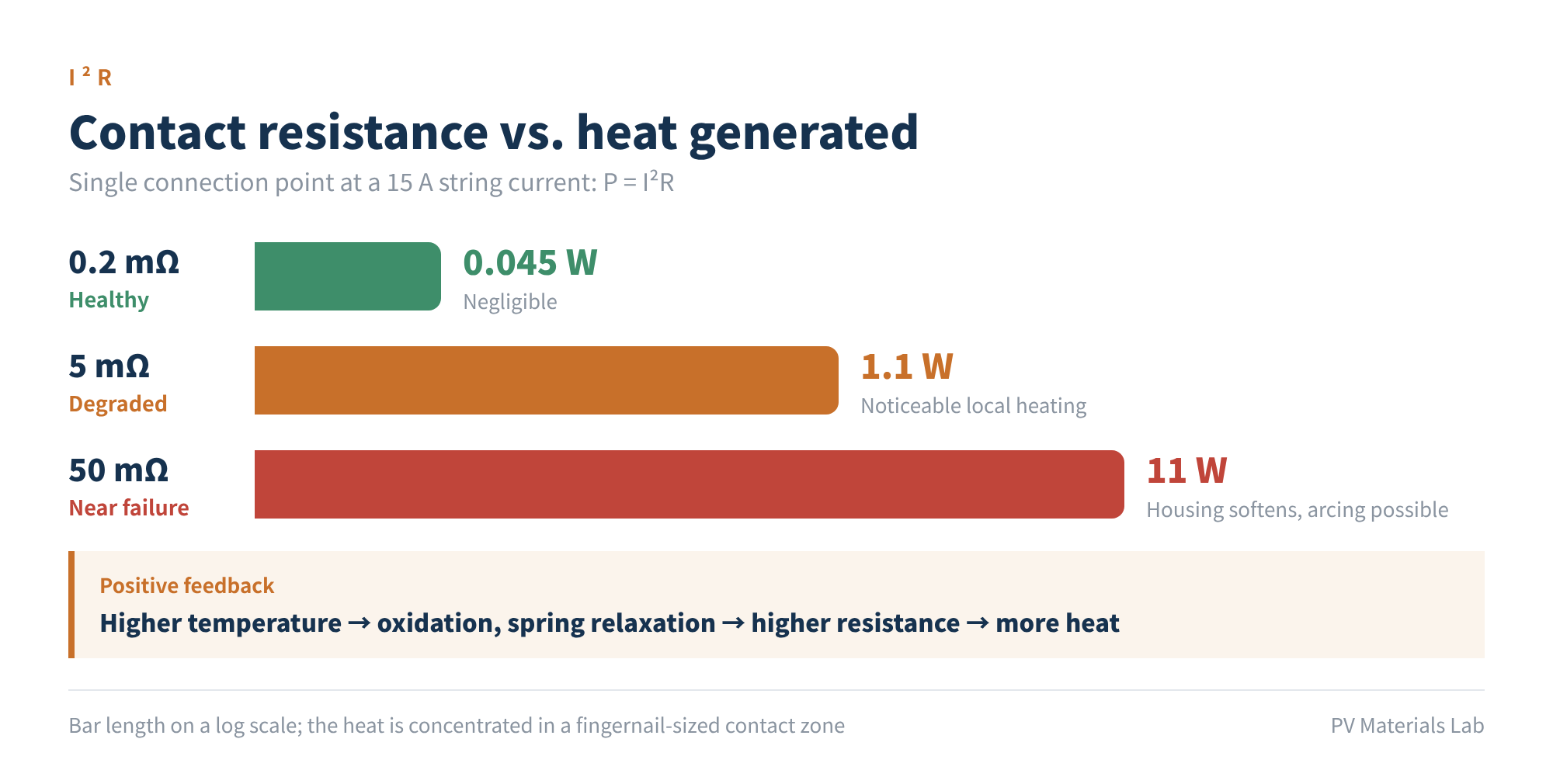
Figure 2 Contact resistance vs. heat generated (at 15 A)
The trouble is that this is a positive-feedback loop. Higher temperature speeds up oxidation of the contacts and relaxes the springs, so contact resistance rises further and more heat is produced, until the housing melts and a DC arc forms. A DC arc has no zero crossing, so it will not extinguish by itself.
So the real test of a connector is whether its contact resistance stays at the factory level after more than twenty years of thermal cycling, damp heat, UV and wind vibration outdoors.
03The MC4's four lines of defence
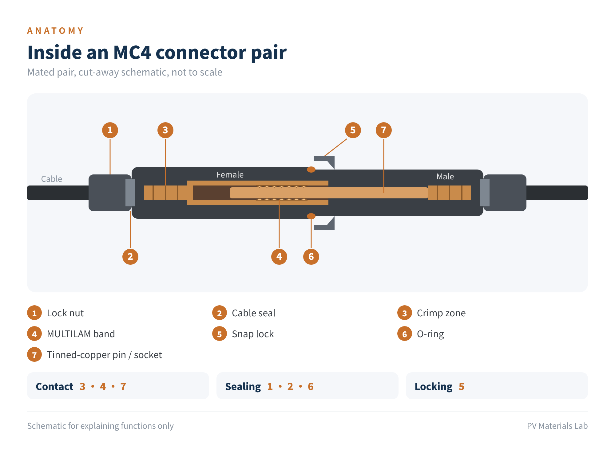
Figure 3 Inside an MC4 connector pair (not to scale)
Line one: contact. At the heart of the MC4 is the MULTILAM contact band: a ring of copper-alloy lamellae stamped into a louvre shape and fitted inside the socket. Each lamella forms its own contact point with the pin, and all of them conduct in parallel.
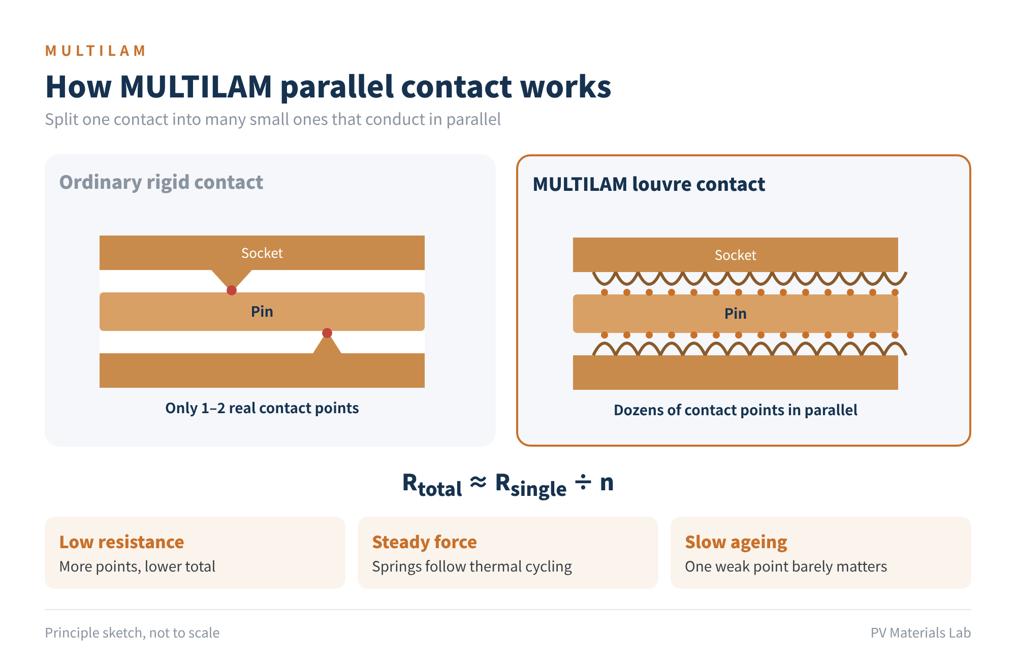
Figure 4 How MULTILAM parallel contact works
Parallel contact brings three benefits. More contact points mean lower total resistance; the MC4-Evo 2 is rated at below 0.2 mΩ. The lamellae keep their spring force, so contact pressure is not lost as parts expand and contract. And if a few points degrade, the rest keep conducting, so overall performance declines only slowly.
Line two: sealing. An O-ring seals the mating face and a seal at the cable end is compressed by the lock nut, giving IP65 / IP68 when mated. If moisture cannot get in, the contacts are much less likely to corrode.
Line three: locking. Once the latch engages, it can only be released with a dedicated tool. Wind vibration and cable pull will not shake it loose, and it cannot be unplugged by accident.
Line four: materials and termination. The contacts are tin-plated copper; the housing is PA (polyamide) engineering plastic with a UL94-V0 flame rating and has passed ammonia-resistance testing. The cable is terminated by crimping.
| Item | MC4-Evo 2 rating |
|---|---|
| Rated voltage | DC 1500 V (IEC / UL) |
| Rated current (IEC) | 2.5 mm² 39 A; 4 mm² 45 A; 10 mm² 69 A |
| Rated current (UL) | Up to 70 A (8 AWG) |
| Contact resistance | < 0.2 mΩ |
| Ambient temperature | −40 to +85 ℃ |
| Upper limiting temperature | 115 ℃ |
| Degree of protection | Mated IP65 / IP68 (1 m, 1 h); unmated IP2X |
| Contact / insulation | Tin-plated copper (MULTILAM) / PA, UL94-V0 |
| Standards | IEC 62852, UL 6703, TÜV, JET; IEC TS 63126 Level 2 |
| Altitude | Up to 5000 m |
Table 1 Main MC4-Evo 2 ratings (source: Stäubli product manual; refer to the latest datasheet)
Notably, this "old" product is moving up with system voltages. In September 2024 Stäubli launched the MC4-Evo 2000, rated for DC 2000 V and up to 70 A, with a housing in a new PC material and crimping that stays compatible with the Evo 2 tooling, in preparation for the next generation of 2000 V PV systems.
04Why customers ask for it by name
- Twenty years of outdoor track record. Type testing can weed out poor products, but it cannot prove a product will last 25 years. The MC4 has more than twenty years in mass production and field records from billions of units, data that a new product simply does not have. This is what investors, banks and insurers mean by "bankability".
- The same-maker, same-type rule. This is the most practical reason. IEC 62852, together with installation standards such as IEC 62548 and IEC 60364-7-712, requires mated plugs and sockets to come from the same maker and be of the same type (or be certified as intermateable). In a plant, modules connect to inverters, combiner boxes, optimisers and extension leads, and much of that equipment ships with Original MC4s. If the module side uses Original MC4 too, the whole DC side is free of cross-mating.
- Full certification, accepted worldwide. Rated 1500 V under both IEC and UL, with TÜV, cULus, JET and other approvals, one part number can serve Europe, North America, Japan, Australia and other markets, so module makers need not switch connectors by market.
- A risk calculation. Connectors are cheap; failures are expensive. A 2019 investigation by TNO in the Netherlands analysed 27 rooftop PV fires (most of them in 2018) and found that about 70% were caused by faulty connectors, especially cross-mating. In a 2017 BRE study of 58 PV-related fires in the UK, DC isolators and poor installation were the most common identified causes. Specifying a long-proven model is one of the cheapest risk controls available.
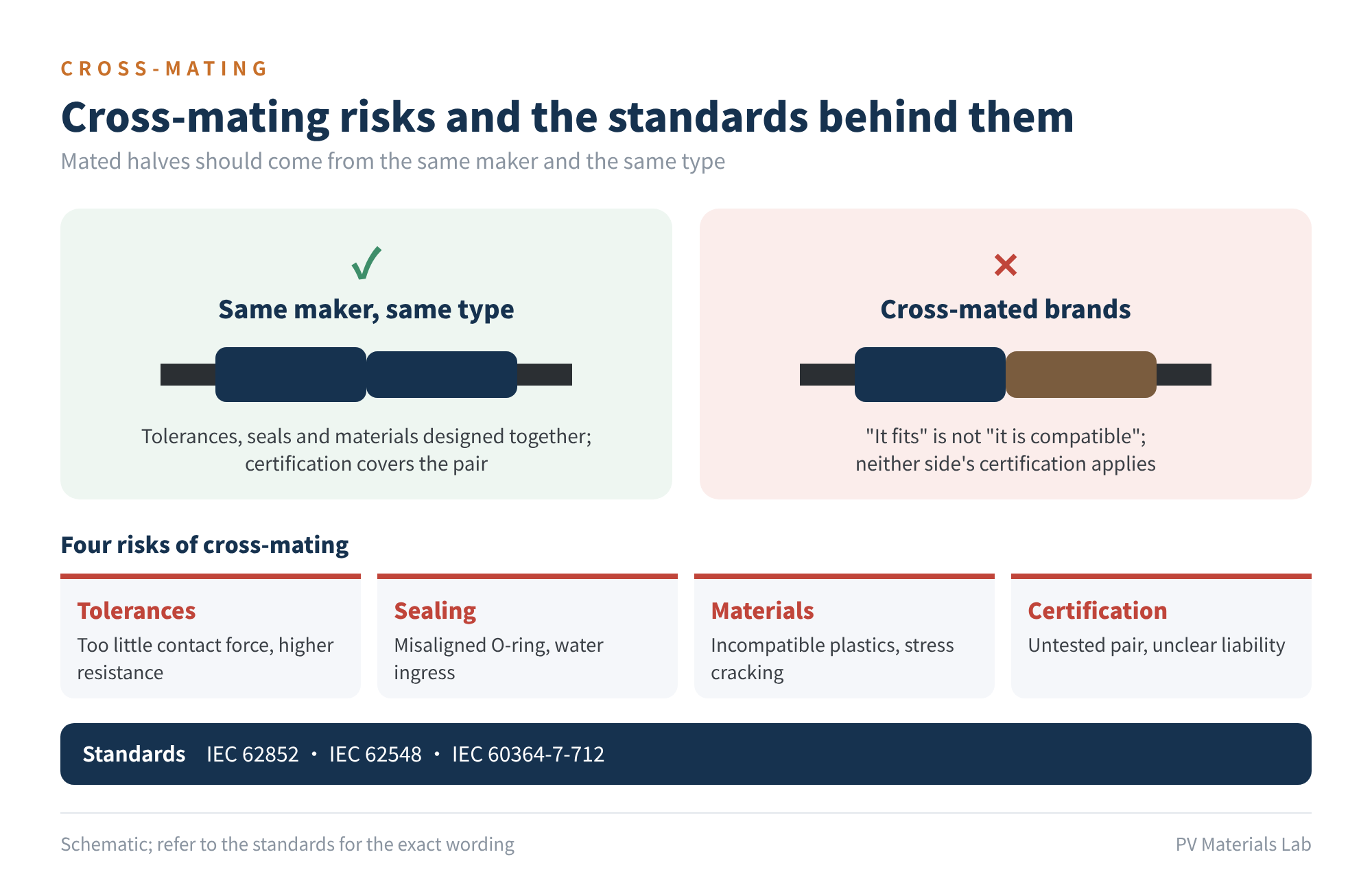
Figure 5 Cross-mating risks and the standards behind them
"It fits" and "it is compatible" are two different things. Makers differ in tolerances, seal design and plastic formulations, so a cross-mated pair can suffer from too little contact force, failed sealing or stress cracking of the housing. Certification only covers combinations that have been tested, and after an incident it is hard to say who is liable. That is why module installation manuals and datasheets normally state the make and type of connector used, and installers should choose mating connectors accordingly.
05Using it well matters more than choosing it
Even the best connector cannot survive poor installation. The most common problems in the field come down to the following points:
- Same maker, same type; never cross-mate. Before connecting to an inverter or an extension lead, check the connector type on both sides.
- Use the maker's specified crimping and torque tools. Field crimping is the weak link. Research cited in PV Tech's review suggests that field-assembled connectors are about 24 times more likely than factory-fitted ones to have insufficient nut torque.
- Keep dust caps on unmated connectors. A few months of exposure can damage both the contacts and the sealing faces.
- Never connect or disconnect under load. A DC arc will erode the contacts.
- Minimise repeated mating. Data cited in the same review show contact resistance rising by about 10% after 10 mating cycles and about 30% after 50.
- Keep them off the ground, out of water and free of strain. Fix connectors to the mounting structure or module frame, and leave a straight run of cable behind each one to avoid bending stress.
New field data back up this advice. In 2025 Sandia National Laboratories published a study in Solar Energy that examined 6,276 connectors removed from 265 rooftop systems installed in 2014–2017. The most common failure causes were too tight a cable bend radius (2.2%), heavy soiling (1.3%) and loose nuts (1.1%). Higher current was associated with higher resistance and more critical failures.
In Sandia's sample, cross-mated connectors showed no clear performance trend versus matched pairs: some cross-mated combinations did fine and others did not. That is exactly the point: the problem with cross-mating is that it is unpredictable and nobody stands behind it, not that it always fails.
06Final thoughts
The MC4 does not lead by a wide margin on any single specification. Chinese connector makers have improved quickly, and many of their products post type-test results that are just as good.
Its advantage is three things stacked together: a design that starts from contact physics, twenty years of field data from billions of units, and the ecosystem effect of the same-maker, same-type rule. Project owners who specify it are buying certainty. As system voltages move from 1500 V towards 2000 V, that certainty will only be worth more.
Connector reliability is half selection and half installation.
Have your projects run into burnt or cross-mated connectors? We would be glad to hear from you.
References
- Stäubli website: Original MC4 / PV module manufacturer pages; cross-connection topic page
- Stäubli: MC4-Evo 2 product manual (11014101); MC4-Evo 2000 product manual (11014087)
- TaiyangNews: "Staubli's Latest PV Connectors For DC Side Installation", Oct 2024
- IEC 62852:2014+AMD1:2020; IEC 62548; IEC 60364-7-712; IEC TS 63126
- pv magazine: "Cross-mating of connectors was chief cause of Netherlands PV fires", Apr 2019 (TNO report)
- Energy Voice: "Poor installation to blame for solar PV fires, says government report" (BRE report)
- PV Tech: "The illusion of simplicity: Why PV DC connector failures remain a persistent challenge"
- pv magazine USA: "Common failure mechanisms for solar connectors", Sep 2025 (Sandia, Solar Energy)
- Wikipedia: Stäubli (company history)
A PV R&D and technology team with 10+ years of experience | In-depth technical knowledge sharing
Materials · Reliability · Failure Analysis · Standards & Certification · Products · Processes
Exploring AI + PV; collaboration welcome
Disclaimer:
1. Original content reflects the authors' personal views only, is for reference only and does not constitute investment advice.
2. Reposted and cited content is credited to its source, out of respect for original work.
3. Some content was produced with AI assistance (chart generation, data retrieval, concept explanations, etc.); the core framework and key content were written by our technical team and reviewed by people.
4. If anything is inaccurate or infringes your rights, please leave a message or contact us and we will deal with it.