
PV PID Series #4: How Is PID Tested, and How Should You Read a Test Report?
PV PID Series · Part 4
The first three articles covered why PID happens. This one takes a different angle: how does a lab find out whether a module resists PID? And how should you read the "PID test passed" report a manufacturer hands you?
01What a PID test does
Outdoors, PID is a slow process measured in years, and a lab cannot wait that long. The idea of a test is to turn the factors from Part 3 all "up to the maximum" at once, forcing problems out within days:
| Knob | Outdoors | In the lab |
|---|---|---|
| Voltage | Varies with position and light | Maximum system voltage, held constant |
| Temperature | Varies by day, night and season | Constant 60 °C or 85 °C |
| Surface conductivity | Occasional dew or rain | Constant high humidity, or conductive foil applied directly |
| Time | Several years | Tens to hundreds of hours |
There are two ways to "make the glass surface conductive", and they correspond to two kinds of test method.
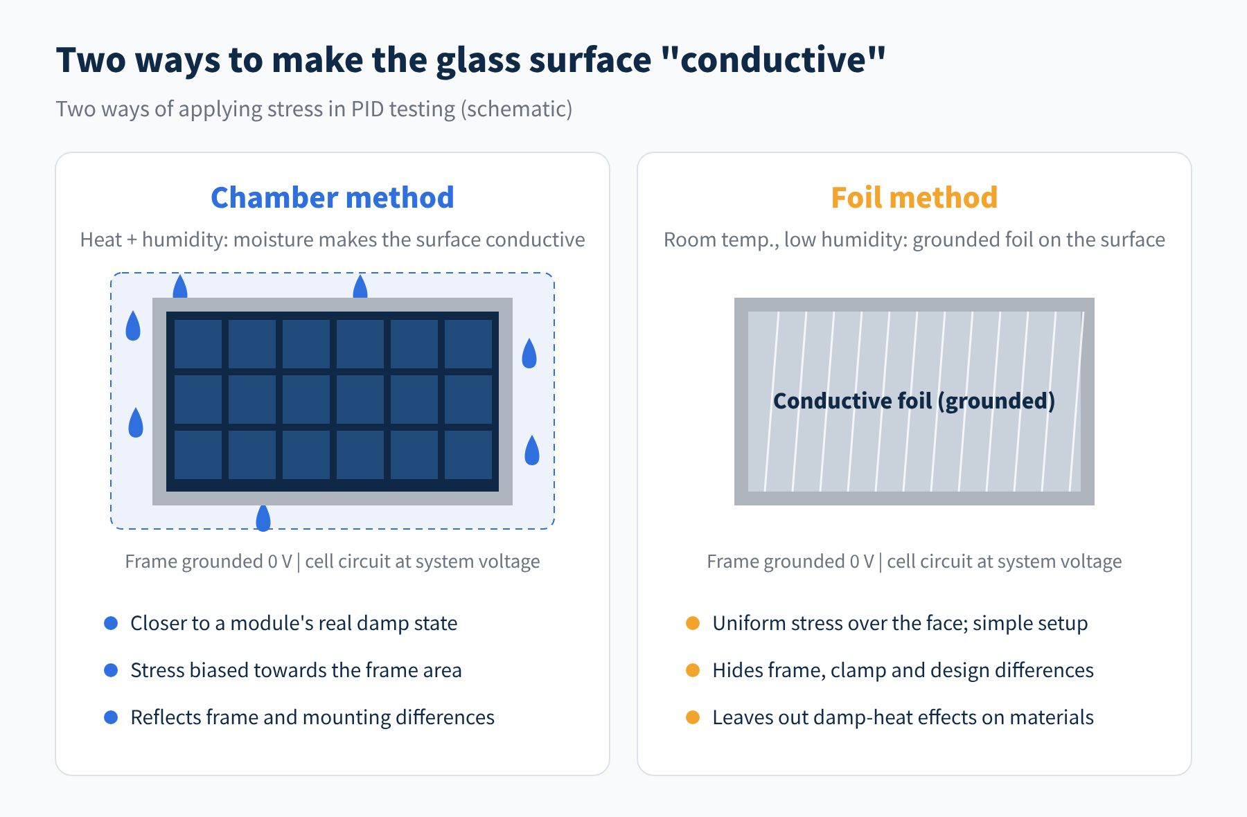
Figure 1 Two ways of applying stress in PID tests: chamber method and foil method
- Chamber method: the module goes into a hot, humid climate chamber, and moisture makes its surface conductive. This is closer to a module's real damp state, but stress tends to concentrate near the frame, with the middle of the module stressed less.
- Foil method: at room temperature and lower humidity, conductive foil is applied over the whole surface and grounded. Stress is uniform over the face and the setup is simple, but it "flattens out" design differences such as frames, clamps and mounting, and it leaves out the effect of damp heat on the materials themselves.
Results from the two methods are not equivalent. Both are "screening tests", and neither includes every factor that affects the rate of PID in the natural environment. This is stated in the body of the standard and is worth remembering when reading reports.
02A map of the standards
For PID testing of crystalline-silicon modules, these are the three kinds of document you meet most often.
IEC TS 62804-1: how to test for PID
This is the "method standard" (a technical specification) for PID testing. Edition 1, published in 2015, defined the two dark test methods above; a common example condition is 60 °C, 85 % relative humidity and 96 hours.
In June 2025, Edition 2 was published and replaced Edition 1. There are two main changes: a new test procedure specifically for PID-p that brings UV light into the test, and a new procedure for measuring how far PID-p recovers under UV light. The new edition applies to modules with silicon cells that have passivating dielectric layers; thin-film, tandem and heterojunction modules are outside its scope, though it can serve as guidance.
IEC 61215-2:2021: PID in module qualification
IEC 61215 is the design qualification standard for crystalline-silicon modules. The 2021 edition added a PID test (MQT 21), which references IEC TS 62804-1 and uses 85 °C, 85 % relative humidity and 96 hours at the module's rated maximum system voltage. If the module is not restricted to one grounding polarity, both polarities must be tested.
Note that in IEC 61215-1:2021 the pass criteria for MQT 21 are mainly no major visual defects and acceptable wet leakage current, with the power loss recorded in the report. The often-quoted "no more than 5% loss" is usually an extra criterion set by customer contracts or certification bodies, not a uniform threshold for this test.
Third-party extended testing: longer duration plus recovery
Certification answers "pass or fail"; it cannot tell "good" from "better". So the industry widely uses stricter third-party tests. Take Kiwa PVEL's Product Qualification Program (PQP): still 85 °C and 85 % relative humidity, but the duration doubles to 192 hours, with negative polarity as the primary test and positive-polarity results also reported. Samples with marked loss get a short UV exposure to see how much of the loss is reversible PID-p.
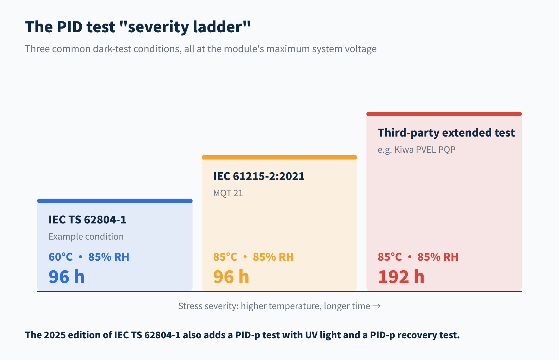
Figure 2 Three common dark PID test conditions
| Document | Role | Typical conditions |
|---|---|---|
| IEC TS 62804-1 | Test method (technical specification) | Example: 60 °C / 85 % RH / 96 h; 2025 edition adds UV and recovery |
| IEC 61215-2:2021 MQT 21 | One test in module design qualification | 85 °C / 85 % RH / 96 h, maximum system voltage |
| Third-party extended test | Benchmarking, procurement basis | 85 °C / 85 % RH / 192 h, both polarities, with recovery assessment |
03How a test runs from start to finish
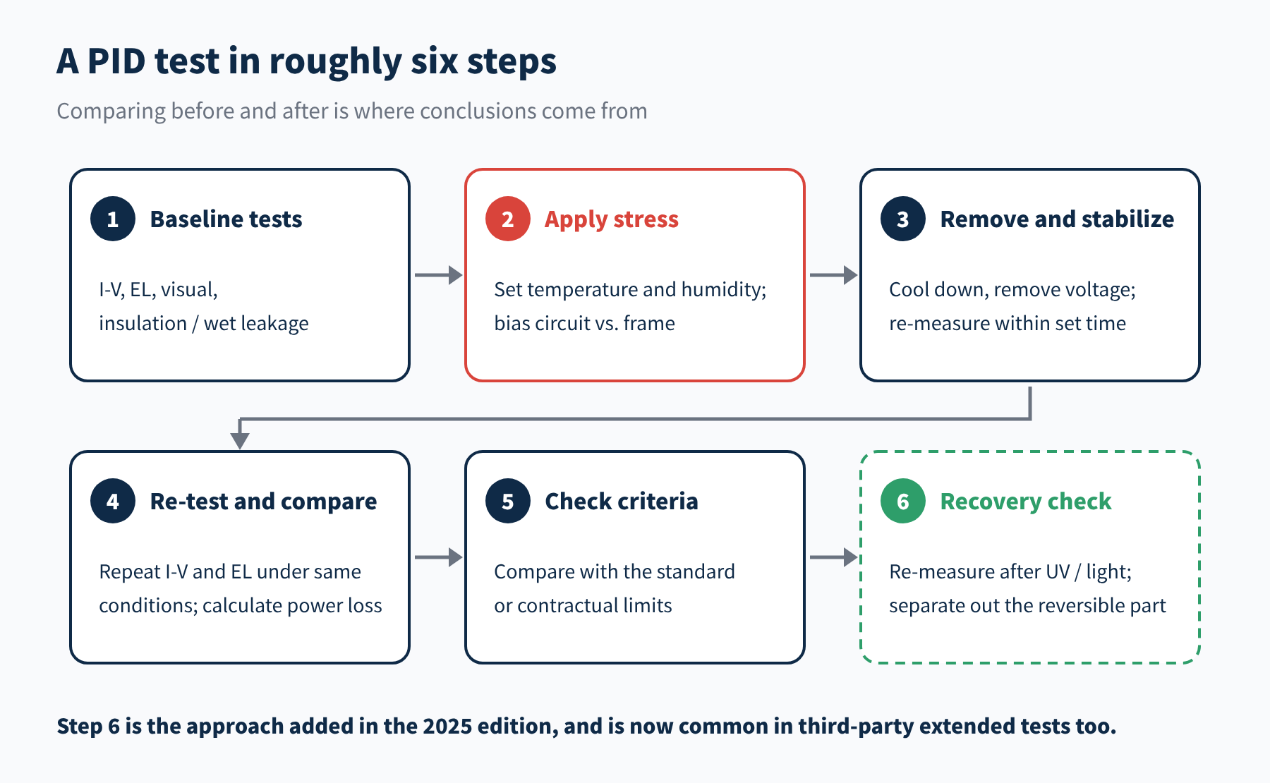
Figure 3 Basic flow of a PID test
The flow itself is simple: full baseline characterization, apply stress, remove the module and re-measure within a set time, then compare the before-and-after power against the criteria. A few details decide whether the data can be trusted:
- How the voltage is applied. The module frame is grounded and voltage is applied between the cell circuit (with positive and negative leads shorted together) and the frame. Negative versus positive voltage corresponds to the module sitting at the negative or positive end of a string.
- Initial state. The module must be stabilized before testing, or other effects such as light-induced degradation will get mixed into the result.
- Timing of the re-measurement. PID-p recovers on its own once the voltage is removed, and faster under light. How long passes between removal and measurement, and whether the module sees light in between, both affect the reading.
04Why light is being added to the test
Traditional PID tests are all run in the dark. For PID-s in p-type cells that is fine: sodium-induced shunts do not disappear in light.
PID-p is different. As Part 2 noted, light, especially UV, lets built-up charge drain away. Outdoors, a module is under voltage and in sunlight at the same time during the day, so real degradation is far smaller than in a dark test. In the NREL TOPCon test cited in that article, the loss was about 30% in the dark but only about 3% on average with UV.
In other words, a dark test is a "worst case" for PID-p and can clearly overstate real outdoor losses. Overstating is not bad in itself, but it distorts comparisons between technologies. The 2025 edition of IEC TS 62804-1 adds UV light and recovery tests precisely to bring results closer to the field.
This adds a new point to check in reports: for the same module, "loss after 96 hours in the dark" and "loss after recovery" can be very different numbers, so make sure you know which one the report gives.
05Six questions to ask of a report
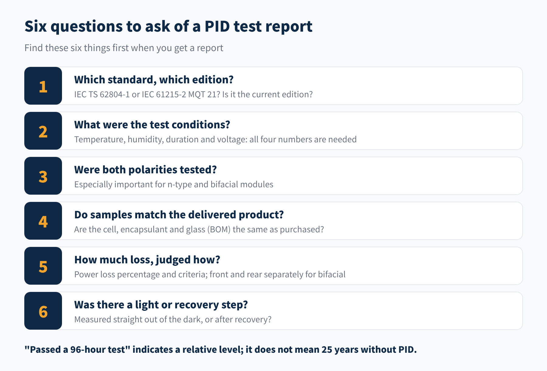
Figure 4 Six things to confirm when reading a PID test report
- ① Standard and edition. IEC TS 62804-1:2015 was replaced by the new edition in June 2025. Older reports are not invalid, but be aware they do not include a PID-p test with light.
- ② Test conditions. 60 °C and 85 °C differ greatly in severity, and 96 hours is a very different test from 192 hours. A bare "passed the PID test" with no conditions tells you little.
- ③ Polarity. In the p-type era only negative bias mattered. For n-type and bifacial modules the sensitive polarity depends on the design, so data for both polarities should be there.
- ④ Sample BOM. As Part 3 showed, the encapsulant and cell coatings have a huge effect on PID. If the test sample used POE but deliveries switched to EVA, the report does not represent the modules you receive.
- ⑤ Results and criteria. Look at the actual percentage loss, not just "pass". For bifacial modules, check front and rear power changes separately, because rear-side PID is easily hidden by front-side data. EL comparison images are a plus.
- ⑥ Light and recovery. Was the data measured straight out of the dark, or after light or UV recovery? Both are useful, but they must not be compared with each other.
These are not standard terms; no standard defines "zero PID". They usually just mean "passed a test under certain conditions". To judge what they are worth, go back to the six questions above.
06Where the industry stands today
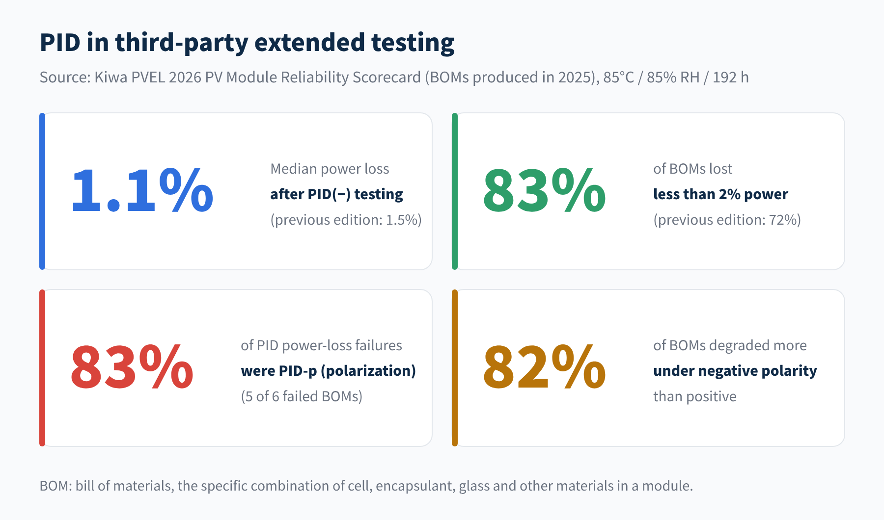
Figure 5 PID test data from the Kiwa PVEL 2026 Scorecard
Kiwa PVEL published the 12th edition of its Scorecard in May 2026, covering BOMs produced in 2025. After 192 hours of negative-polarity extended testing, median power loss was 1.1% (previous edition: 1.5%), and 83% of BOMs lost less than 2% (previous edition: 72%), so PID resistance among mainstream products is improving overall. Still, 15% of BOMs had at least one failure in PID testing; besides power loss, failures included delamination, safety and bypass-diode issues.
Two other numbers are more telling: among BOMs with PID power-loss failures, 83% (5 of 6) were PID-p, and 82% of BOMs degraded more under negative polarity. This matches the earlier articles: in the n-type era, the lead role in PID has passed from sodium shunting to polarization, and the negative end is still where it hits hardest.
07Final thoughts
● A PID test is accelerated screening that maxes out voltage, temperature and surface conductivity together; there are chamber and foil methods.
● IEC TS 62804-1 defines the methods, and its 2025 edition adds a PID-p test with UV light and a recovery test; MQT 21 in IEC 61215-2 brings PID into module qualification.
● Dark tests can overstate outdoor PID-p losses, so distinguish "before recovery" from "after recovery" when reading results.
● When reading a report, ask six things first: standard, conditions, polarity, BOM, results and recovery.
With theory and testing covered, the final article goes back to the field: when a plant shows suspected PID, how do you investigate and recover it, and how should new projects prevent it? We will wrap up the series next time. This is Part 4 of our PV PID series; stay tuned, and we would be glad to hear from you.
References
- IEC TS 62804-1:2025 (Ed. 2), Photovoltaic (PV) modules – Test methods for the detection of potential-induced degradation – Part 1: Crystalline silicon: webstore.iec.ch
- IEC 61215-1:2021 / IEC 61215-2:2021, Terrestrial photovoltaic (PV) modules – Design qualification and type approval (MQT 21)
- Kiwa PVEL, 2026 PV Module Reliability Scorecard – PID: scorecard.pvel.com/pid
- PV Tech: Module test failures continue to increase in Kiwa PVEL’s 2026 Module Reliability Scorecard: pv-tech.org
- P. Hacke, et al. Field-representative evaluation of PID-polarization in TOPCon PV modules by accelerated stress testing. Progress in Photovoltaics 32(5), 2024. NREL/JA-5K00-88644
A PV R&D and technology team with 10+ years of experience | In-depth technical knowledge sharing
Materials · Reliability · Failure Analysis · Standards & Certification · Products · Processes
Exploring AI + PV; collaboration welcome
Disclaimer:
1. Original content reflects the authors' personal views only, is for reference only and does not constitute investment advice.
2. Reposted and cited content is credited to its source, out of respect for original work.
3. Some content was produced with AI assistance (chart generation, data retrieval, concept explanations, etc.); the core framework and key content were written by our technical team and reviewed by people.
4. If anything is inaccurate or infringes your rights, please leave a message or contact us and we will deal with it.