
DH1000 Damp Heat Testing of PV Modules: Test Conditions, Failure Signatures and Failure Mechanisms (TOPCon as an Example)
Key points
- Unchanged conditions: the DH1000 conditions (85 °C / 85 % RH / 1000 h) have barely changed in over 30 years, yet what the industry expects from the test keeps quietly rising.
- Four things under test: encapsulants, edge sealing, cell metallization and passivation layers, and the backsheet.
- Typical signatures: Rs rises and FF falls; EL shows dark cell edges and darkened fingers.
- TOPCon mechanism: galvanic corrosion of the front Ag/Al paste, compounded by passivation degradation and ionic contamination.
DH1000 (Damp Heat, 1000 hours) is one of the most classic and important basic environmental tests in PV module type approval and reliability assessment. It is defined by the International Electrotechnical Commission (IEC) in IEC 61215-2, test MQT 13 "Damp Heat Test", and its purpose fits in one sentence: to determine the module's ability to withstand long-term moisture penetration.
This article goes through DH1000 in order: what the conditions are, what the test challenges, what failure looks like, why modules fail, and how to analyse a failure.
01DH1000 test conditions
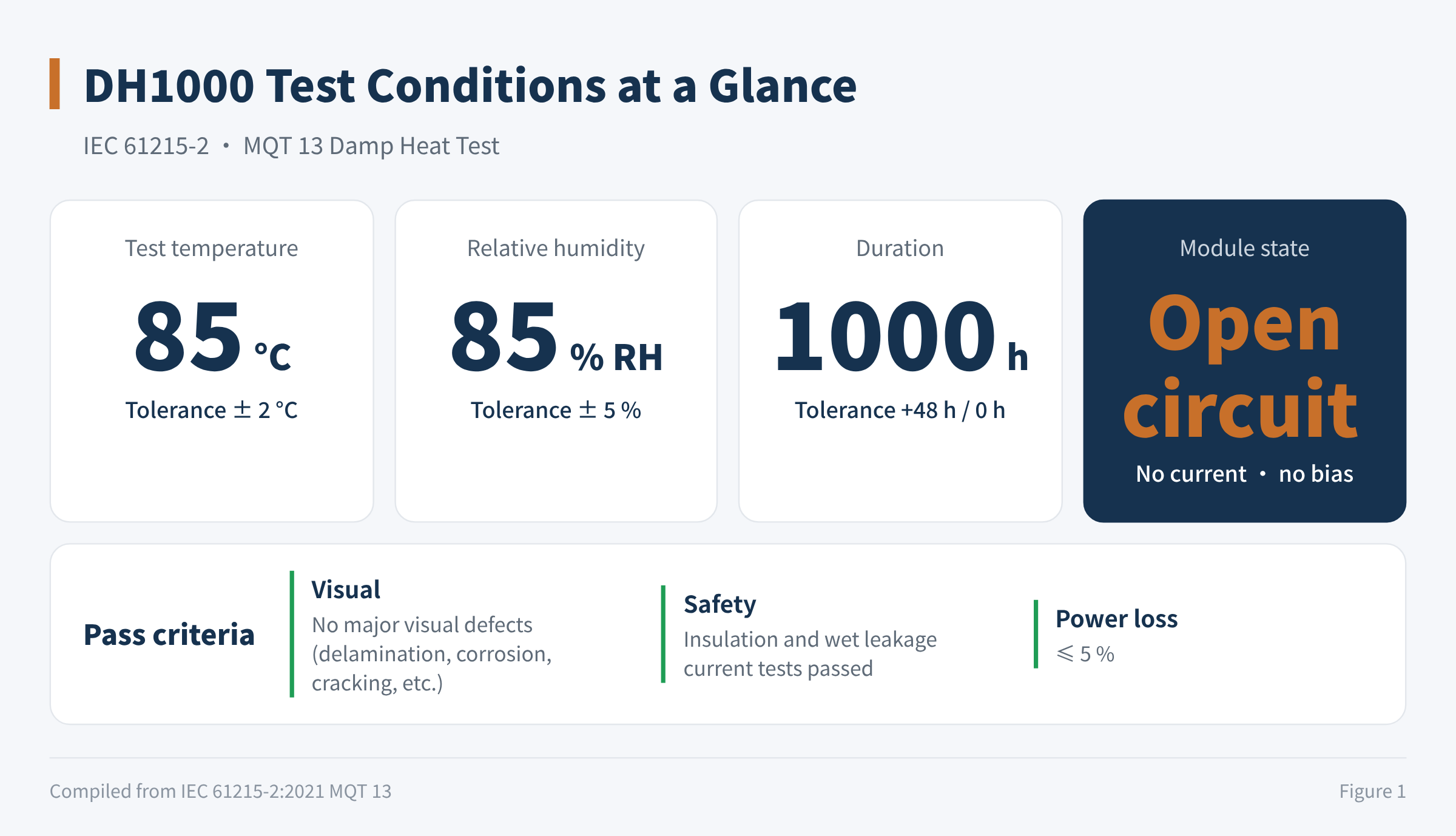
Figure 1 DH1000 test conditions at a glance
| Item | Requirement |
|---|---|
| Test temperature | 85 °C ± 2 °C |
| Relative humidity | 85 % ± 5 % RH |
| Duration | 1000 h (tolerance +48 h / 0 h), continuous, without interruption |
| Preconditioning | None |
| Module state | Open circuit, no current and no applied bias |
The module state deserves emphasis: during DH testing the module is open-circuited and no bias is applied. This is the most fundamental difference from PID testing. PID examines "heat + humidity + high voltage"; DH examines pure "heat + humidity".
Pass criteria:
- Visual: no major visual defects such as obvious delamination, corrosion or cracking.
- Safety: insulation and wet leakage current tests both passed.
- Power loss: ≤ 5 % (judged on the final power at the end of the test sequence).
02The standard hasn't changed, but the bar keeps rising
The physical conditions of DH1000 (85 °C / 85 % RH / 1000 h) were already set in the first edition of IEC 61215 in 1993 and have not fundamentally changed in more than 30 years; the current IEC 61215:2021 still uses them. But judging by how the industry actually applies it, and by what leading manufacturers and buyers require, it has quietly been upgraded three times.
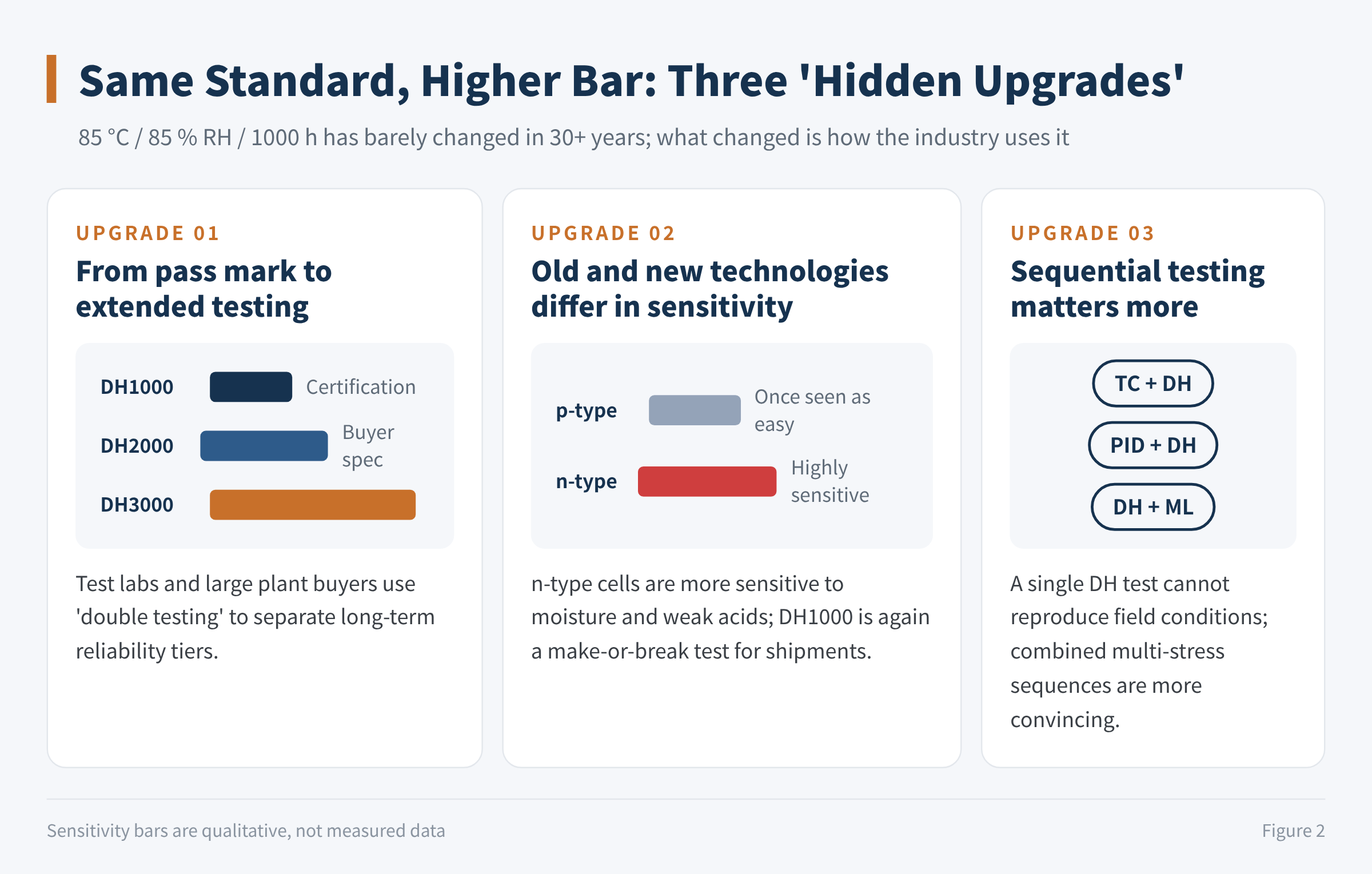
Figure 2 Three "hidden upgrades" of DH1000
1. From pass mark to extended testing (DH2000 / DH3000)
In the early days of conventional glass-backsheet modules, passing DH1000 was widely seen as the basic threshold for backing a 25-year warranty, even though field performance at many sites fell short of expectations. With glass-glass modules now mainstream and encapsulation processes mature, DH1000 has long stopped being a bottleneck for tier-one manufacturers.
Independent test labs and large utility-scale buyers therefore began writing "double testing" into procurement specifications, i.e. DH2000 or even DH3000, to separate modules into long-term reliability tiers. The extended-stress testing in IEC TS 63209-1 also includes DH2000.
2. Old and new technologies differ in sensitivity
The test itself hasn't changed, but how hard it hits new technologies has. In the p-type era, the industry largely considered DH1000 a non-issue. In the n-type era, cells have become noticeably more sensitive to moisture and weakly acidic environments, and DH1000 has once again become a make-or-break test that limits yield and shipments for many second- and third-tier manufacturers.
3. Sequential testing matters more and more
A single DH1000 run can never reproduce real field conditions. Recent standards and third-party programmes put more weight on sequential test results such as TC + DH, PID + DH and DH + ML, combining multiple stresses to reproduce severe field degradation more realistically.
03What does DH1000 actually test?
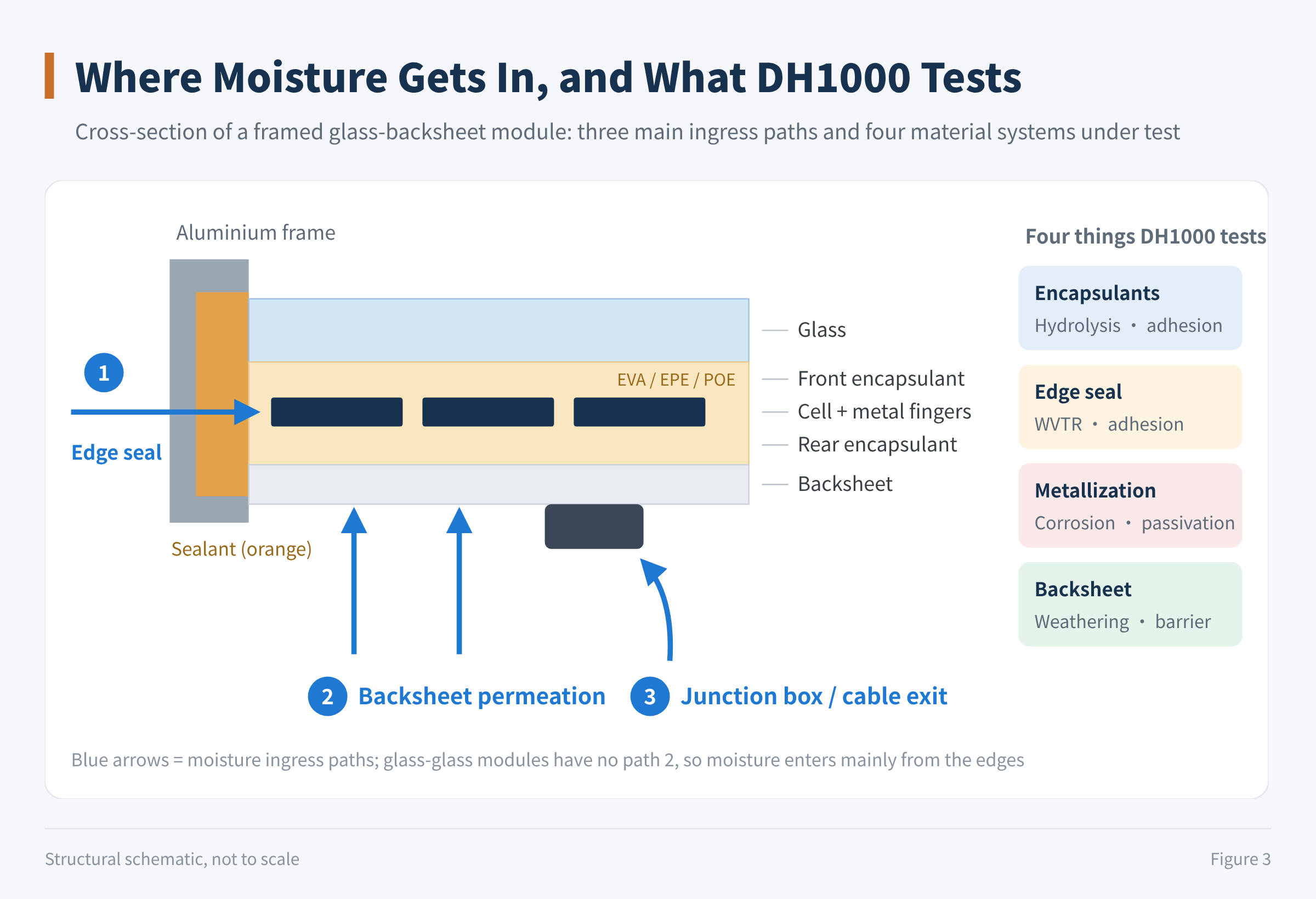
Figure 3 Moisture ingress paths and the four things DH1000 tests
1. Moisture barrier and chemical stability of the encapsulants
- Hydrolysis resistance: how far the encapsulant (EVA, EPE, POE) hydrolyses under heat and humidity. EVA hydrolyses easily in this environment and releases acetic acid; POE is more stable but more expensive.
- Interfacial adhesion: moisture penetration breaks the chemical bonds at the glass/encapsulant, encapsulant/cell and encapsulant/backsheet interfaces. With insufficient adhesion, the module delaminates over large areas.
2. Reliability of the edge-seal system
For framed modules, DH1000 is a severe test of the moisture-barrier performance of sealants such as silicone, double-sided tape or butyl. If the sealant's water vapour transmission rate is too high, or its adhesion to the aluminium frame or glass fails under damp heat, moisture quickly gets in from the module edge.
3. Corrosion resistance of cell metallization and passivation layers
- Corrosion resistance of the metal fingers: the ability of front and rear Ag and Ag/Al pastes to resist electrochemical corrosion in an environment containing free ions and moisture. This is exactly the main challenge for TOPCon cells.
- Stability of the antireflection and passivation layers: whether the silicon nitride (SiNₓ) and aluminium oxide (Al₂O₃) on the cell surface hydrolyse and lose hydrogen under heat and humidity directly determines whether passivation is maintained.
4. Weathering resistance and barrier performance of the backsheet
For glass-backsheet modules, the backsheet is the first line of defence against moisture. DH1000 directly exposes the weaknesses of poor-quality backsheets: yellowing, embrittlement or even cracking, after which moisture floods in.
04DH1000 failure signatures
1. Electrical degradation
| Parameter | Typical change | Notes |
|---|---|---|
| FF | Clear decrease | The most characteristic signature |
| Rs | Clear increase | Goes hand in hand with the FF drop |
| Isc | Slight decrease | Relatively small change |
| Voc | Little change | A mild-to-moderate drop indicates passivation damage |
| Pmax | Overall loss | The combined result of the above |
Below are measured data for one TOPCon module before and after DH1000:
| Stage | Pmax (W) | Isc (A) | Voc (V) | Ipm (A) | Vpm (V) | FF | Rs (Ω) | Rsh (Ω) |
|---|---|---|---|---|---|---|---|---|
| Initial | 639.24 | 14.69 | 53.193 | 13.99 | 45.684 | 0.82 | 0.317 | 362.4 |
| After DH1000 | 626.98 | 14.57 | 53.097 | 13.89 | 45.142 | 0.81 | 0.334 | 337.5 |
| Change | −1.92 % | −0.78 % | −0.18 % | −0.74 % | −1.19 % | −0.97 % | +5.24 % | −6.89 % |
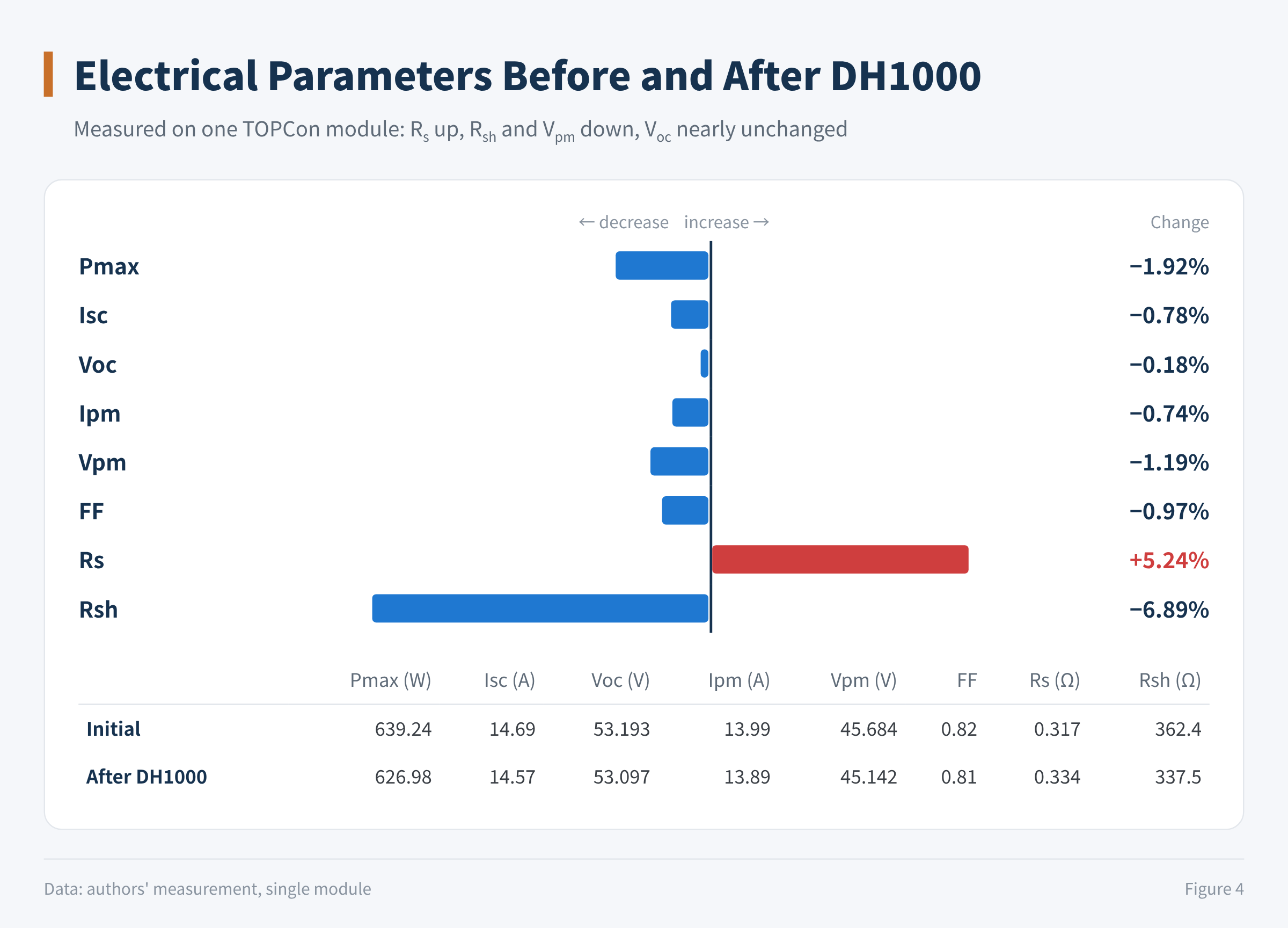
Figure 4 Electrical parameters before and after DH1000
This module lost 1.92 % of its power, well inside the 5 % limit, so it is a passing sample. But the direction of change is already typical: Rs rose by 5.24 %, FF and Vpm fell with it, while Voc barely moved (−0.18 %).
Rsh also fell by 6.89 %, which points to some leakage paths forming inside the module (for example local leakage caused by ionic contamination). However, Rsh is still in the hundreds of ohms, so its effect on FF is much smaller than that of the Rs increase.
The loss in this module comes mainly from series resistance (the metallization contact), not from passivation.
2. EL signatures
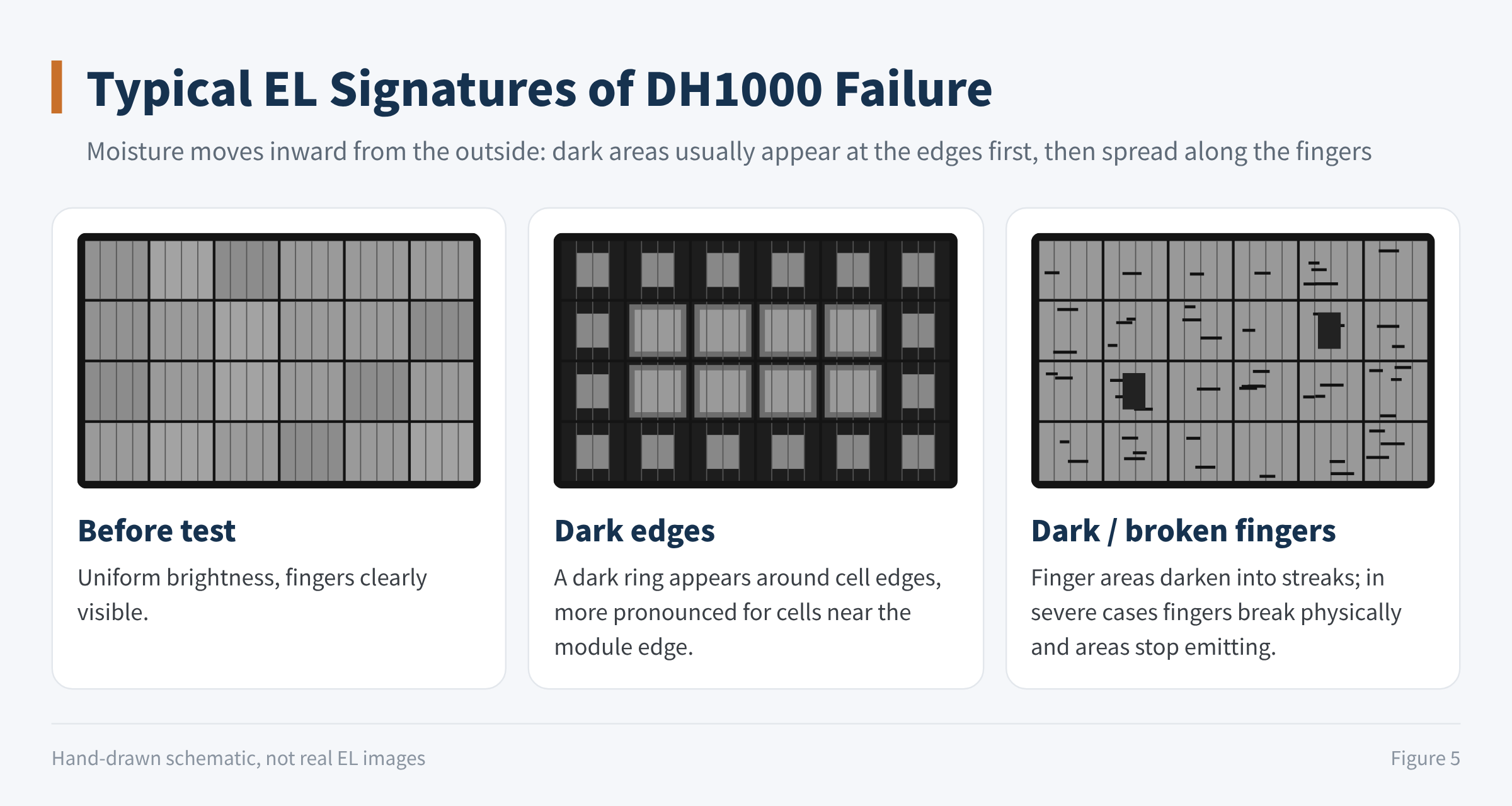
Figure 5 Typical EL signatures of DH1000 failure (schematic)
- Dark edges: moisture usually penetrates inward from the module edge, which shows up in EL as a dark band around the cell edges.
- Dark / broken fingers: the front finger areas darken, and in severe cases physical finger breakage can be seen.
3. Visual appearance (usually only obvious in severe failures)
- Finger discoloration: corrosion discoloration on busbars or fingers.
- Interface delamination: delamination or bubbles at encapsulant interfaces.
- Backsheet ageing: yellowing, embrittlement, etc. of the backsheet on glass-backsheet modules.
05Main DH1000 failure mechanisms (TOPCon as an example)
First, the whole chain:
Moisture ingress → trace acid release from the encapsulant → galvanic corrosion of front Ag/Al paste / dehydrogenation of Al₂O₃ passivation → higher Rs / more recombination → dark edges, dark cells and local dark areas in EL → FF drop → power loss
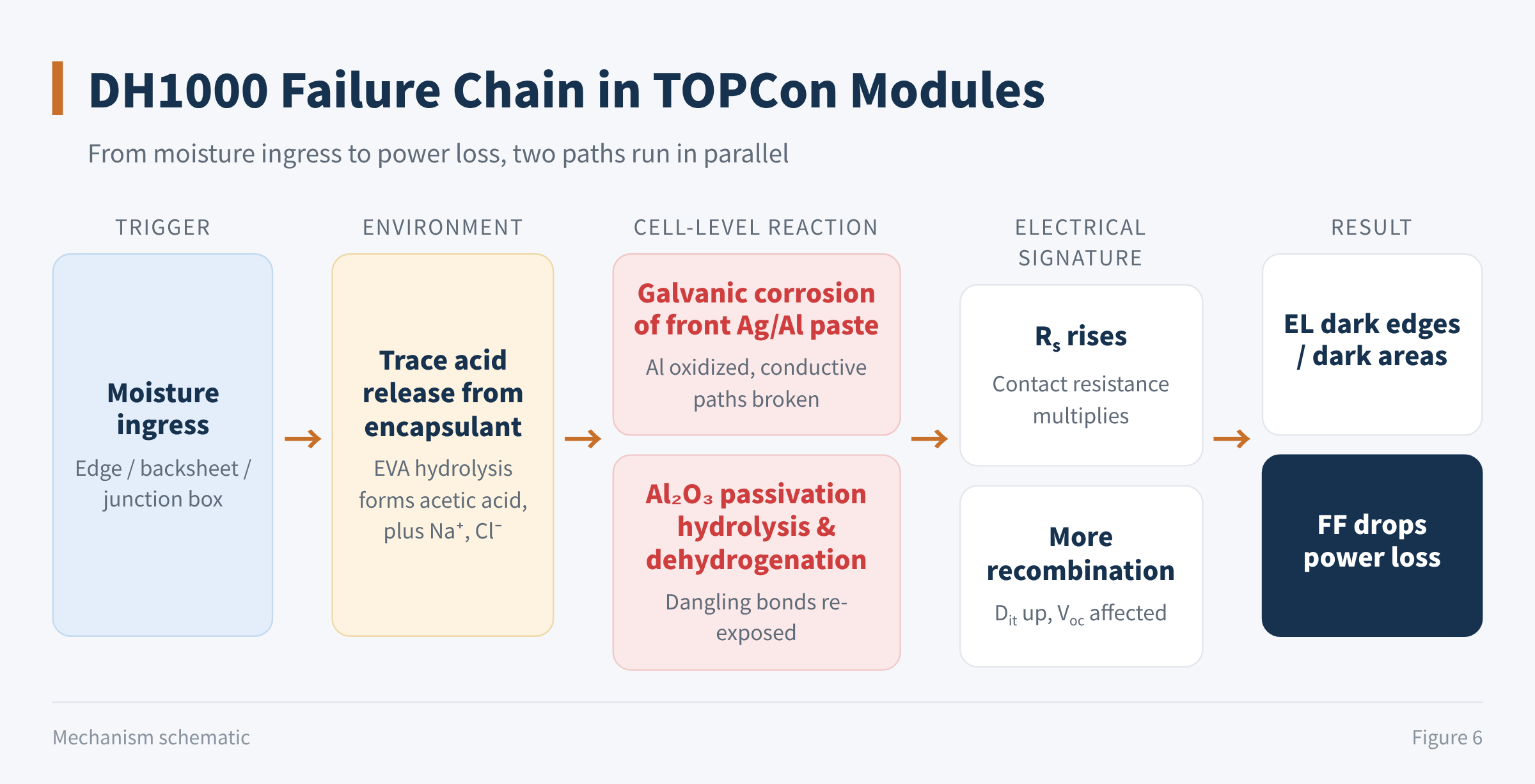
Figure 6 DH1000 failure chain in TOPCon modules
1. Electrochemical corrosion of the front Ag/Al paste (the core pain point)
The front of a TOPCon cell is usually a boron-diffused emitter (p⁺ layer). To fire through the passivation layer and form a good ohmic contact, the front has long relied mainly on Ag/Al paste.
- Galvanic corrosion: silver and aluminium differ strongly in electrochemical potential. Under heat and humidity, moisture passes through the encapsulant to the cell surface and dissolves trace free acid from encapsulant hydrolysis (such as acetic acid) or external impurity ions, forming micro-cells at the Ag, Al and silicon interfaces.
- Sharp rise in contact resistance: the more active aluminium readily loses electrons and is oxidised, forming flocculent, insulating aluminium oxides. The conductive paths between metal grains break, and the contact resistance (Rc) between the metal and the silicon substrate multiplies. This corresponds directly to the macroscopic rise in Rs and drop in FF.
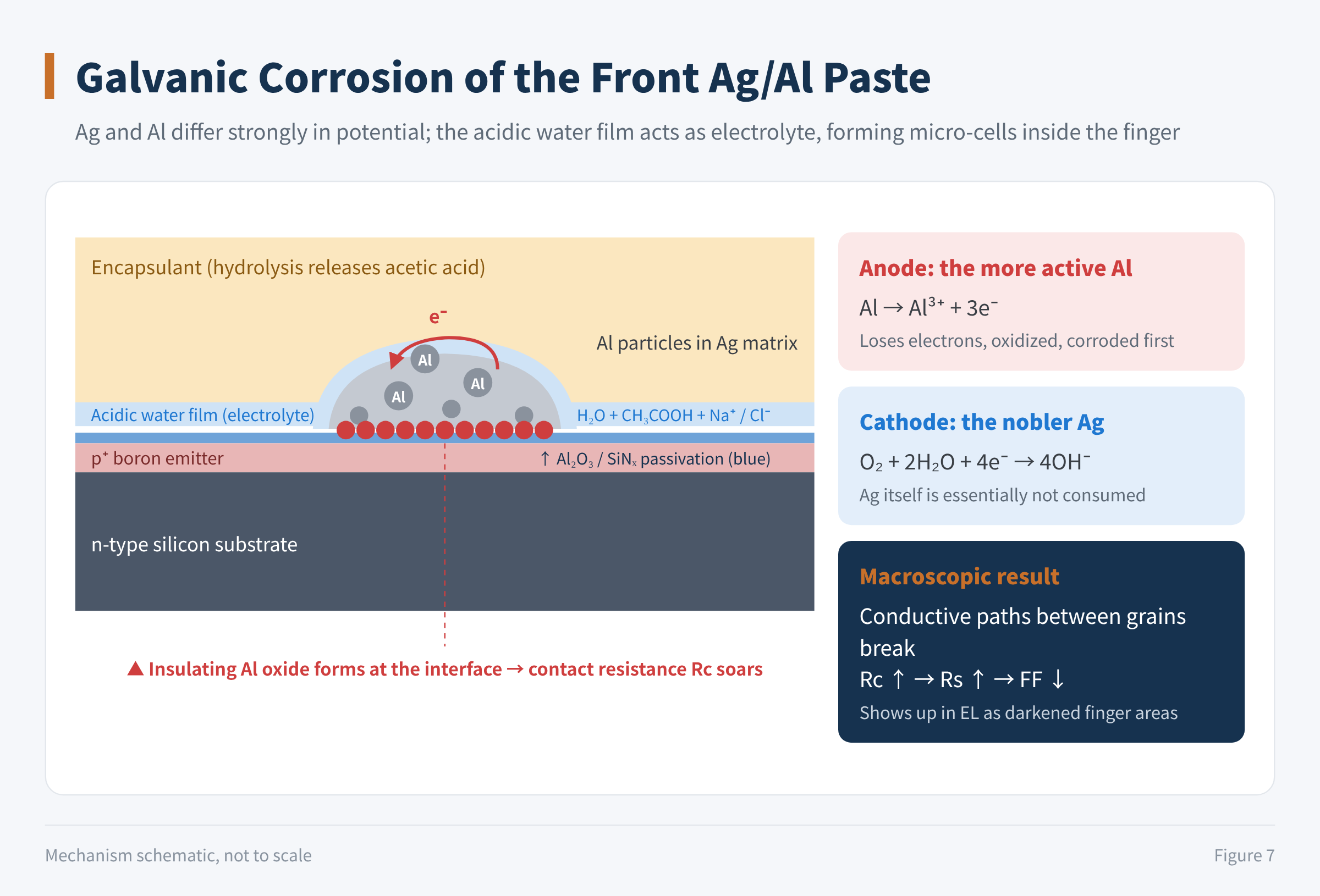
Figure 7 Galvanic corrosion of the front Ag/Al paste (schematic)
The industry's move over the past two years to laser-enhanced contact optimisation (LECO), combined with low-Al or Al-free silver pastes, is to a large extent about cutting off this corrosion pathway at the source. A 2026 study by UNSW and Jolywood also showed that in a mildly acidic environment similar to that inside EVA-encapsulated modules (pH around 5), the series resistance and contact resistivity of Ag/Al contacts rise as acidity increases, making FF loss the main source of power loss, consistent with module-level DH results.
2. Hydrolysis and dehydrogenation of the passivation layer
- Moisture reaching the interface: the rear passivating-contact structure of TOPCon is very dense, but the front Al₂O₃ is highly sensitive to moisture, and ingress causes local hydrolysis of the aluminium oxide layer.
- Hydrogen escape and more interface states: heat and humidity break the Si–H bonds formed during manufacturing. After dehydrogenation, previously passivated silicon dangling bonds are exposed again, the interface defect density (Dit) rises and surface recombination increases.
3. Degradation induced by ionic contaminants
Ionic contaminants come mainly from three sources:
- Glass: Na⁺ and other ions leaching from the glass;
- Handling: Ca²⁺, Cl⁻, sulphur-containing ions, etc. picked up while cells are handled and transferred;
- Flux residue.
Under heat and humidity, these ions readily form an electrolyte. On the one hand they accelerate corrosion at the metal contacts; on the other they increase recombination at the passivation interface.
4. Influence of the encapsulants
Cost-reduced encapsulant combinations inevitably use EVA or EPE films. EVA in particular hydrolyses easily under prolonged heat and humidity and releases acetic acid. Acetic acid acts as a "catalyst": it not only accelerates the Ag/Al galvanic corrosion described above but also corrodes the ribbons, busbars and their solder joints.
06How to analyse a failure: one flowchart
When you actually have a module whose degradation after DH1000 exceeds the limit, the approach can be summarised as: confirm the failure first; classify it preliminarily using I–V, EL and visual inspection; tear down and localise the problem according to the failure mode; then build the failure chain and close the loop with verification. The goal is to determine whether the problem lies in encapsulation, materials, process or design.
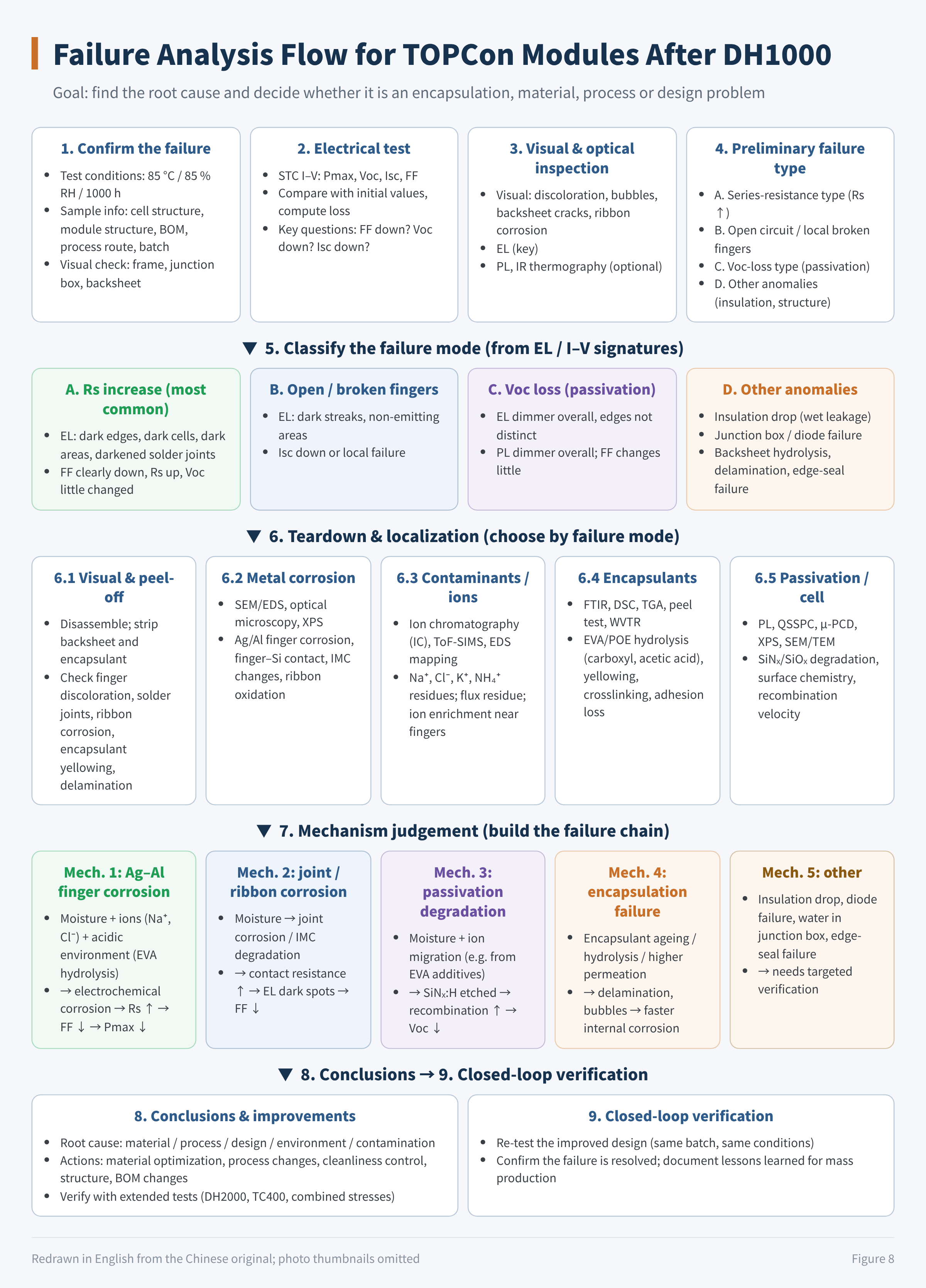
Figure 8 Failure analysis flow for TOPCon modules after DH1000
07Final thoughts
The DH1000 conditions are simple: 85 °C, 85 % RH, 1000 hours, open circuit. The test has become important again in the n-type era because front-side cell metallization is now more sensitive to moisture and acidic environments.
To judge a module's DH performance, focus on three questions:
- Where does the moisture get in: edge seal, backsheet or junction box?
- What does it meet once inside: does the encapsulant release acid, are there ionic residues on the cell surface?
- What fails first at the cell: rising Rs points to metallization corrosion, falling Voc points to passivation degradation.
If you have seen different failure behaviour in your own testing, we would be glad to hear from you.
References
- IEC 61215-1:2021 / IEC 61215-2:2021, Terrestrial photovoltaic (PV) modules – Design qualification and type approval (MQT 13 Damp Heat Test)
- IEC 61215:1993, Crystalline silicon terrestrial photovoltaic (PV) modules – Design qualification and type approval (first edition)
- IEC TS 63209-1:2021, Photovoltaic modules – Extended-stress testing – Part 1: Modules
- X. Wu et al., Bridging accelerated cell-level degradation to module-relevant failure mechanisms in TOPCon solar cells and modules, Chemical Engineering Journal, 2026
A PV R&D and technology team with 10+ years of experience | In-depth technical knowledge sharing
Materials · Reliability · Failure Analysis · Standards & Certification · Products · Processes
Exploring AI + PV; collaboration welcome
Disclaimer:
1. Original content reflects the authors' personal views only, is for reference only and does not constitute investment advice.
2. Reposted and cited content is credited to its source, out of respect for original work.
3. Some content was produced with AI assistance (chart generation, data retrieval, concept explanations, etc.); the core framework and key content were written by our technical team and reviewed by people.
4. If anything is inaccurate or infringes your rights, please leave a message or contact us and we will deal with it.