
Read the IEC 61215 Test Sequence in Ten Minutes with AI
Key points
Four steps, four prompt templates and one sequence map. At the end: the main changes in the 2021 edition, and the three places AI most often gets wrong when reading standards.
The first time they open IEC 61215-1, most people get stuck at the same place: the test flow chart in Figure 2. Twenty-odd MQT numbers, several parallel branches, arrows that split and merge.
Each condition is familiar on its own (anyone can recite DH1000 and TC200), yet put together they are hard to explain. Why does TC50 follow UV instead of TC200? Why does mechanical load wait until damp heat is done? What does each of the two gates judge?
These questions used to be answered by mentors and years of projects. Now there is another way: read with AI. It can't read the original for you, but it can break a dense chart down into a structure you can explain back.
Below are four steps that take about ten minutes in total, followed by the "sequence map" you should carry in your head once you understand it.
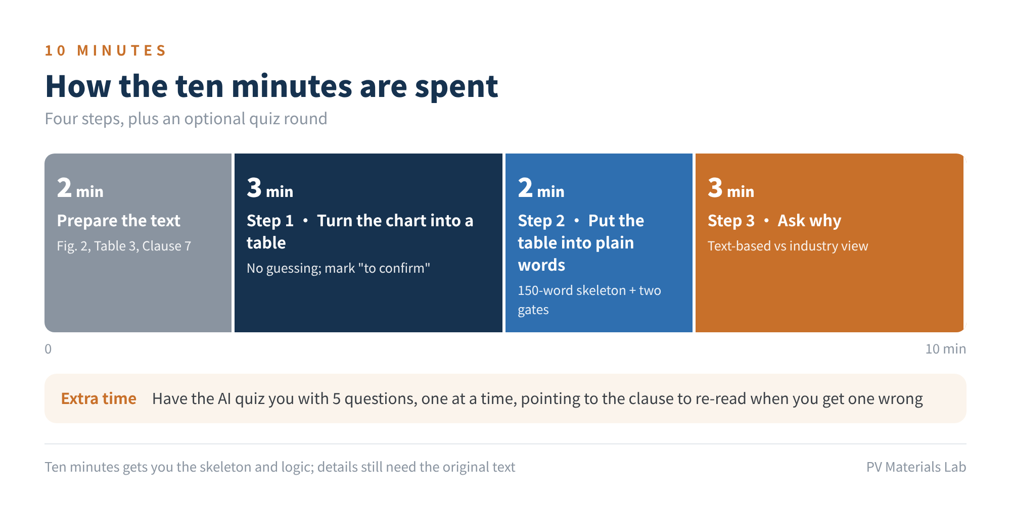
Figure 1 How the ten minutes are spent
00First, what ten minutes gets you
Ten minutes gets you the skeleton and the logic: how many branches there are, what each one simulates, why they are ordered as they are, and how pass or fail is judged. How to select samples, set up equipment or handle deviations still means going back to the original, clause by clause.
There is also a precondition: you must supply the original text. Ask "what is the IEC 61215 test sequence?" directly and the AI can only answer from memory, where the 2005, 2016 and 2021 editions are all mixed together.
01Prepare the text (about 2 minutes)
The three things you need are all in IEC 61215-1:
- Figure 2: the full test flow chart, the thing this article sets out to understand.
- Table 3: the summary of test levels, with the conditions for each MQT.
- Clause 7: the pass criteria, with the definitions and formulas of the two gates.
To go deeper into how a particular test is done, add the corresponding MQT clause in IEC 61215-2. Special requirements for crystalline silicon modules are in IEC 61215-1-1.
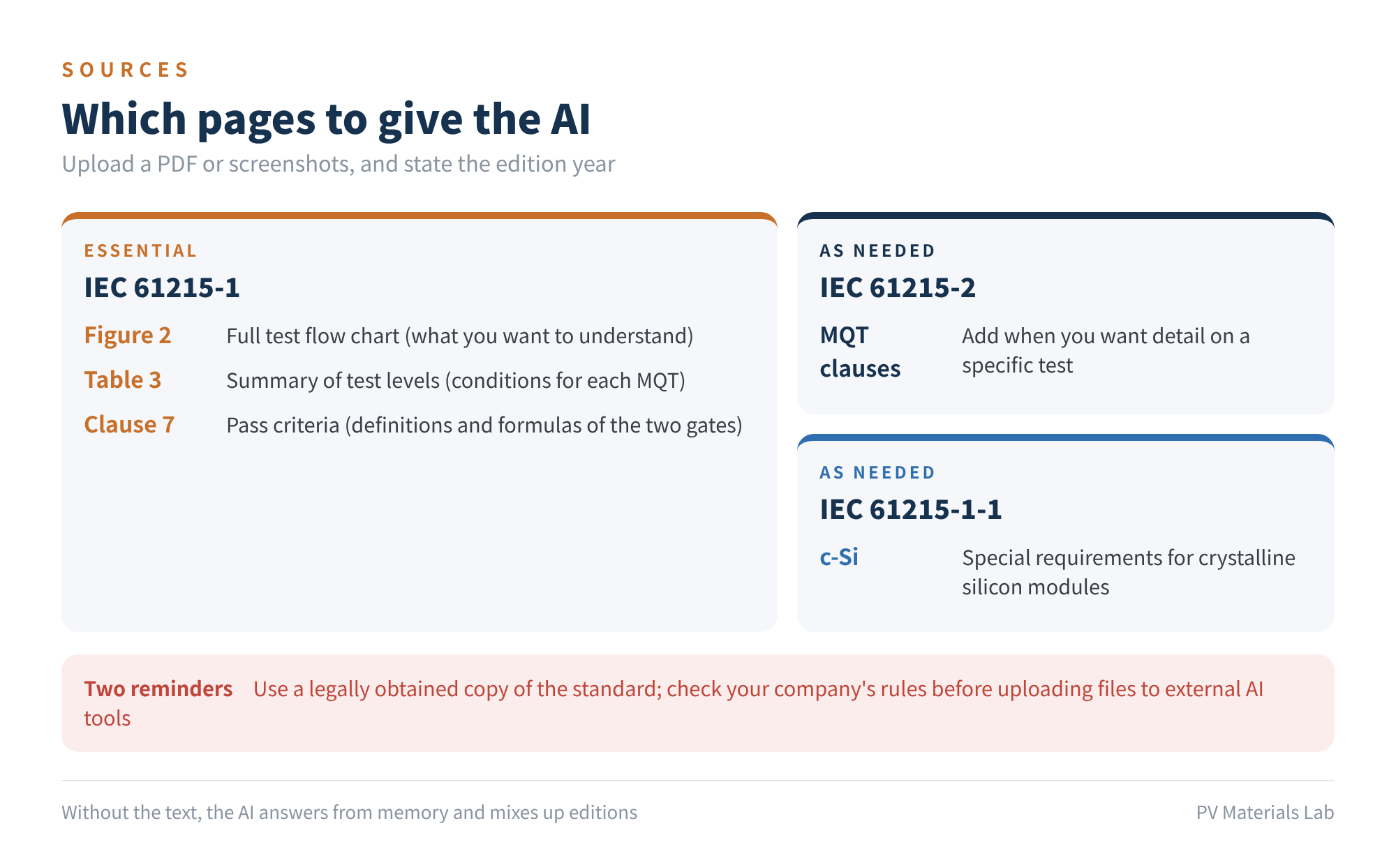
Figure 2 Which pages to give the AI
A PDF or screenshots both work. Two reminders: use a legally obtained copy of the standard, and if your company has rules on uploading files to external AI tools, check them first.
02Step 1: turn the chart into a table (about 3 minutes)
Flow charts are unfriendly to people, and just as unfriendly to AI. So the first job is to have it transcribe the chart into a table; every later question builds on that table.
You are a PV module certification engineer familiar with the IEC 61215 series.

I have uploaded the following from IEC 61215-1:[edition year]:
[Figure 2 test flow chart, Table 3 summary of test levels, Clause 7 pass criteria]

[Task]
1. Transcribe the flow chart into a table: branch / number of samples / tests (in order) / MQT number / test conditions;
2. Separately list the initial and final tests common to all branches;
3. Mark any arrows or numbers in the chart that are unclear or whose direction you cannot determine as "to confirm"; do not guess.

[Constraints]
· Use only what I uploaded; do not fill gaps from other editions you remember;
· For each row of the table, note whether the information comes from Figure 2, Table 3 or the clause text.

[Output]
One table + a list of items to confirm.
Why it is written this way:
- "To confirm" is the key phrase. Arrow directions and sample numbers in the chart are where AI most often misreads. Forbid guessing and it will hand over what it isn't sure of.
- Once the table is out, check it against the original chart yourself. Don't skip this minute. If the table is wrong, every explanation after it will be wrong too.
03Step 2: put the table into plain words (about 2 minutes)
With the table in hand, you can have it explain things to you.
Based on the table above:

[Task]
1. In one sentence per branch, explain what kind of outdoor stress the branch simulates and which failure modes it mainly targets;
2. In no more than 150 words, summarise the skeleton of the whole test programme so that a new engineer could repeat it back after hearing it;
3. Explain what Gate No.1 and Gate No.2 each judge, what each symbol in the formulas means, and what the comparison baseline is.

[Constraints]
· Failure modes are your engineering interpretation, not text from the standard; put them in a separate column labelled "interpretation";
· For the pass criteria, map each sentence to the clause number in the original.

[Output]
Branch table → skeleton summary → interpretation of pass criteria.
Why it is written this way:
- The 150-word limit. It forces the AI to distil the skeleton. If something can't be said briefly, it usually hasn't been understood, for AI and people alike.
- Interpretation separate from the original. "This branch targets delamination" is an engineering reading; the standard says no such thing. Keep them apart and you know what can be quoted and what is only for reference.
04Step 3: ask why (about 3 minutes)
Remembering the order is easy; understanding it is hard. This step pays off most, and needs the most caution.
For each of the following orderings, explain the possible design intent:

· Why do TC50 and HF10 follow UV preconditioning, while TC200 is a separate branch?
· Why do static mechanical load and hail come after damp heat?
· Why are TC50 and HF10 still needed after cyclic mechanical load?

[Constraints]
· The standard text usually doesn't explain reasons. Split your answers into two categories: "supported by the text" (cite the clause) and "common industry understanding" (state that it is inference);
· Where different views exist, list them all rather than giving just one.

[Output]
One paragraph per question: conclusion first, then the type of basis.
Why it is written this way:
- Standards say what to do, not why. So what AI gives you here is almost all inference. Inference can be illuminating, but it must be labelled as inference.
- Ask for different views. The same ordering often has more than one explanation in the industry; hearing only one makes it easy to treat as settled.
Extra time: let it quiz you
Now check whether I have really understood:

1. Set 5 questions covering test order, test conditions and pass criteria, from easy to hard;
2. Ask one at a time, review my answer, then ask the next;
3. Where I get one wrong, tell me which clause of the original to re-read.
If you'd rather not be quizzed, upload the old edition as well and ask for a four-column comparison: "clause / old edition / new edition / impact on testing".
05Once you understand it: a sequence map
After the four steps, this is the picture you should be left with. The branch numbering and grouping are our simplification for memory; for the sequence letters, sample numbers and exact order in the standard, follow Figure 2 of the original.
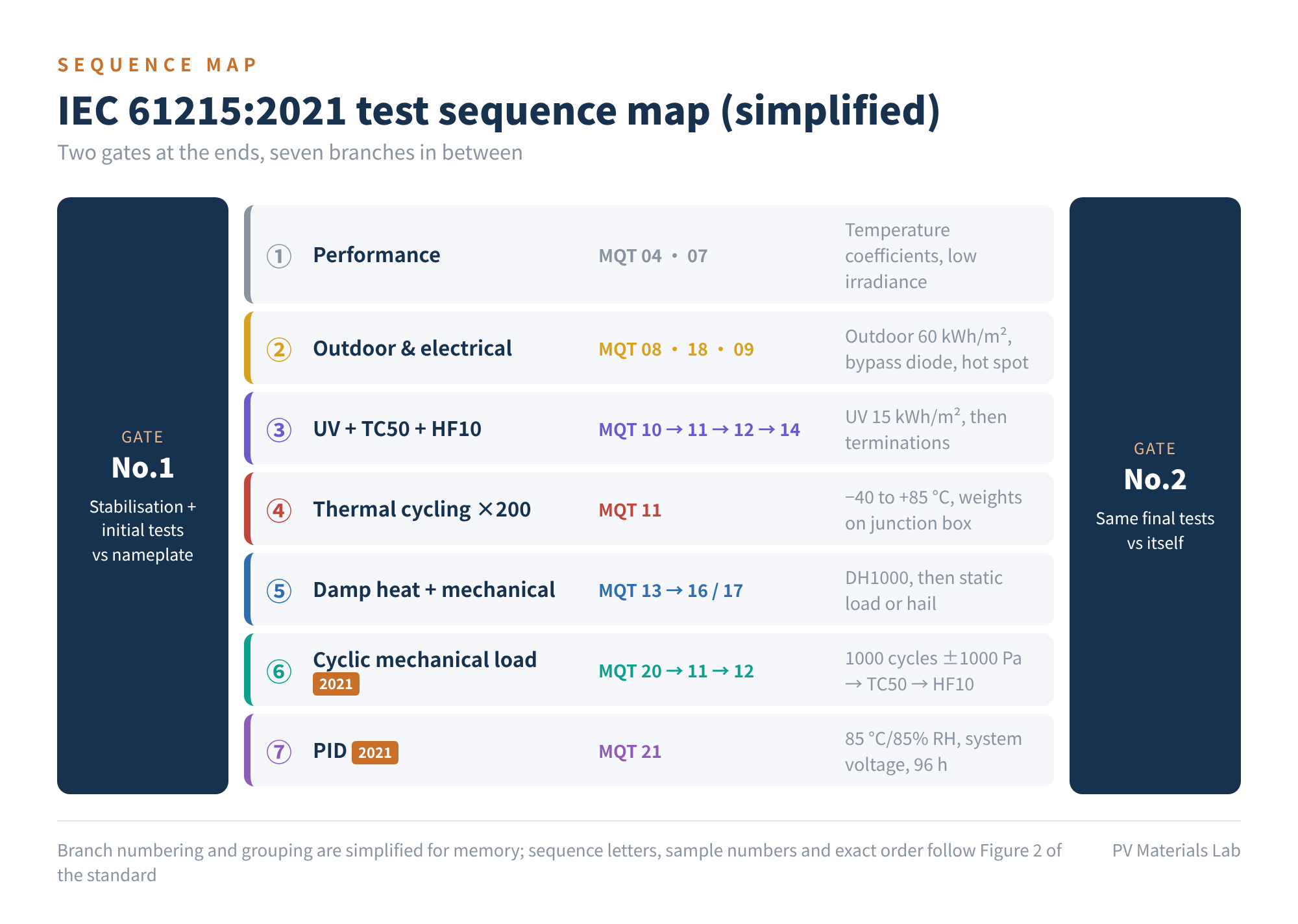
Figure 3 IEC 61215:2021 test sequence map (simplified)
The skeleton in one line: two gates, one at each end, with seven branches in between. All samples are first stabilised and tested, then pass the first gate; they are then split into groups that face different stresses; at the end of each branch they return to the same set of final tests and pass the second gate.
What each gate judges
Gate No.1 judges whether the nameplate is overstated. After stabilisation, each module's measured power, allowing for the lab's measurement uncertainty m1, must exceed the nameplate power minus the lower nameplate tolerance t1:
Pmax(Lab) × (1 + m1) > Pmax(NP) × (1 − t1)
Voc and Isc are verified as well, and the standard sets a separate requirement on the average power of the samples; Clause 7 has the details.
Gate No.2 judges how much was lost after stress. At the end of each branch, power must not fall below 95% of its initial value, allowing for measurement repeatability r:
Pmax(Gate 2) > 0.95 × Pmax(Gate 1) × (1 − r)
Note that the baseline is this module's own measurement at Gate No.1, not the nameplate value. The module must also show no major visual defects and pass insulation and wet leakage tests.
One exception is worth remembering: for the PID branch (MQT 21), power loss only has to be reported; pass or fail rests on visual inspection and wet leakage. The often-quoted "PID loss no more than 5%" is usually an extra requirement from customer contracts or certification bodies, not a criterion of IEC 61215-1:2021 itself.
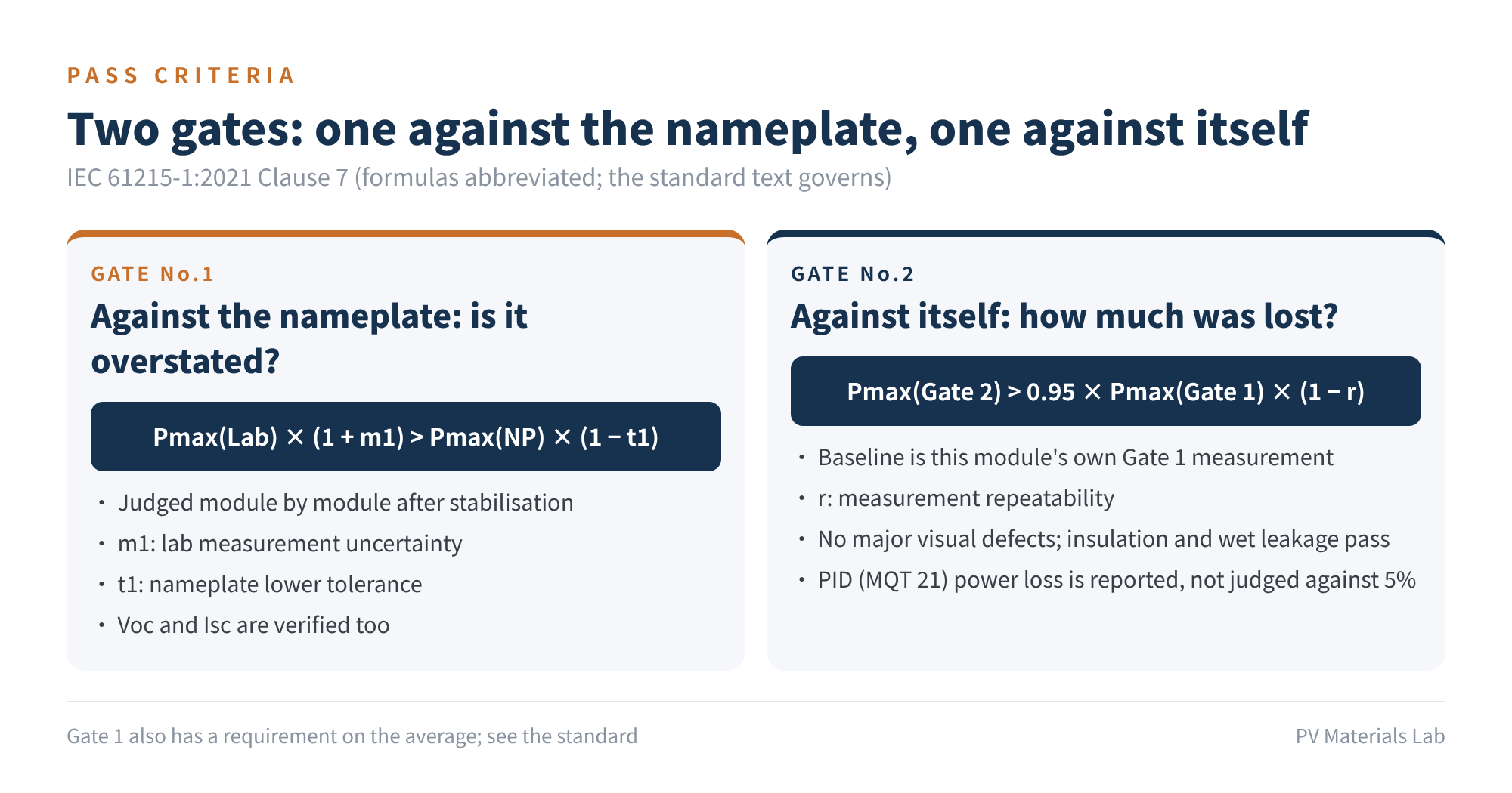
Figure 4 Two gates: one against the nameplate, one against itself
What each of the seven branches simulates
- ① Performance characterisation: MQT 04, MQT 07. No stress; measures temperature coefficients and low-irradiance performance.
- ② Outdoor and electrical stress: MQT 08, MQT 18, MQT 09. Outdoor exposure of 60 kWh/m², bypass diode, hot-spot endurance; targets shading and local overheating.
- ③ UV, thermal cycling, humidity freeze: MQT 10 → 11 → 12 → 14. UV preconditioning of 15 kWh/m², TC50, HF10, then robustness of terminations. Targets encapsulation interfaces: delamination, junction box adhesion and sealing.
- ④ 200 thermal cycles: MQT 11, −40 °C to +85 °C. Targets thermal fatigue of ribbons and solder joints, and growth of cell cracks.
- ⑤ Damp heat plus mechanical: MQT 13 → MQT 16 or MQT 17. 1000 hours at 85 °C/85% RH, followed by static mechanical load or hail. Targets moisture ingress, corrosion, and mechanical strength after ageing.
- ⑥ Cyclic mechanical load: MQT 20 → TC50 → HF10, new in 2021. 1000 cycles at 1000 Pa; targets cell cracks and how they develop.
- ⑦ PID: MQT 21, new in 2021. 85 °C/85% RH with system voltage applied for 96 hours.
The logic behind the order
For the three most frequently asked "whys", the common industry understanding is as follows:
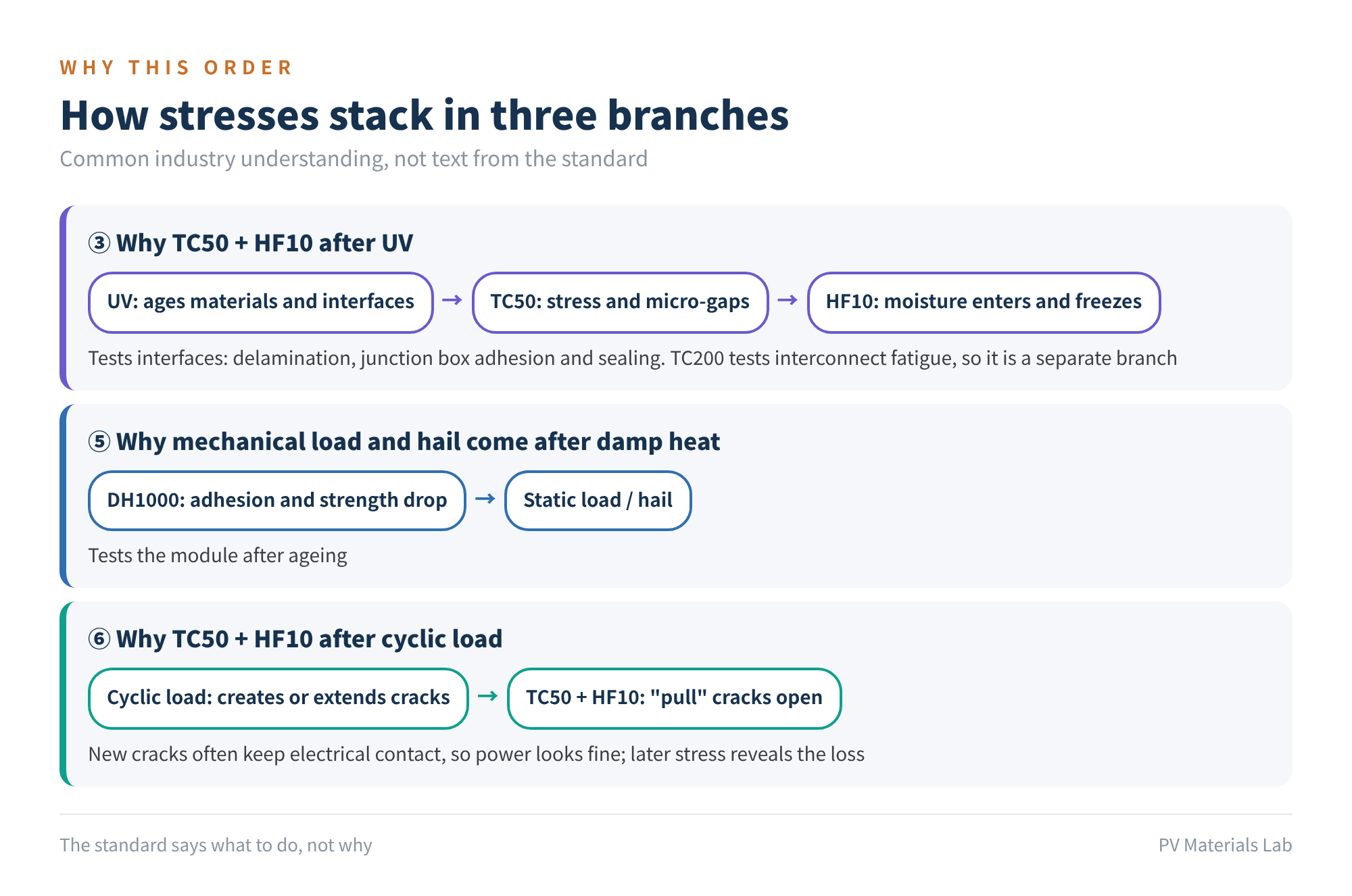
Figure 5 How stresses stack in three branches (common industry understanding, not text from the standard)
- Why TC50 plus HF10 after UV. This branch tests interfaces. UV first ages the encapsulant and bonded interfaces, thermal cycling creates stress and tiny gaps, and humidity freeze then lets moisture in and freezes it. Only with all three stacked do delamination and sealing problems show up. TC200 tests fatigue of metal interconnects, a different problem, so it has its own branch.
- Why mechanical load and hail come after damp heat. After damp-heat ageing, adhesion and strength both decline. Loading the module then tests it in its aged state.
- Why TC50 plus HF10 after cyclic load. Cyclic load can create or extend cell cracks, but when cracks first appear the fragments often still make electrical contact, so power looks unchanged. The thermal cycling and humidity freeze that follow "pull" the cracks open and the loss becomes visible.
06What changed from 2016 to 2021
If your experience is still based on the 2016 edition, these points need updating:
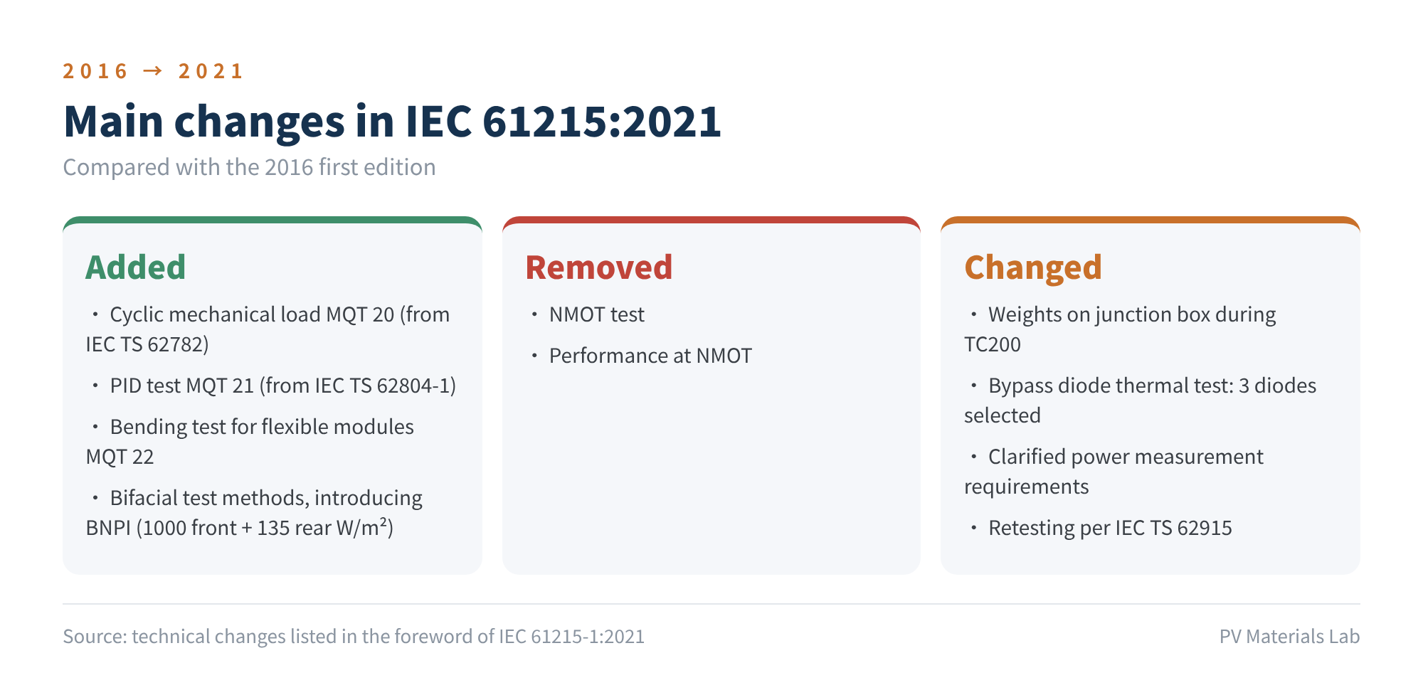
Figure 6 Main changes in IEC 61215:2021
- Added: cyclic mechanical load MQT 20 (from IEC TS 62782); PID test MQT 21 (from IEC TS 62804-1); bending test for flexible modules MQT 22; definitions and test methods for bifacial modules, introducing the BNPI irradiance condition of 1000 W/m² on the front plus 135 W/m² on the rear.
- Removed: the NMOT test and the performance test at NMOT.
- Changed: weights attached to the junction box during TC200; the bypass diode thermal test now selects 3 diodes; clarified requirements for power measurement; retesting to follow IEC TS 62915.
07Three places AI most often gets wrong
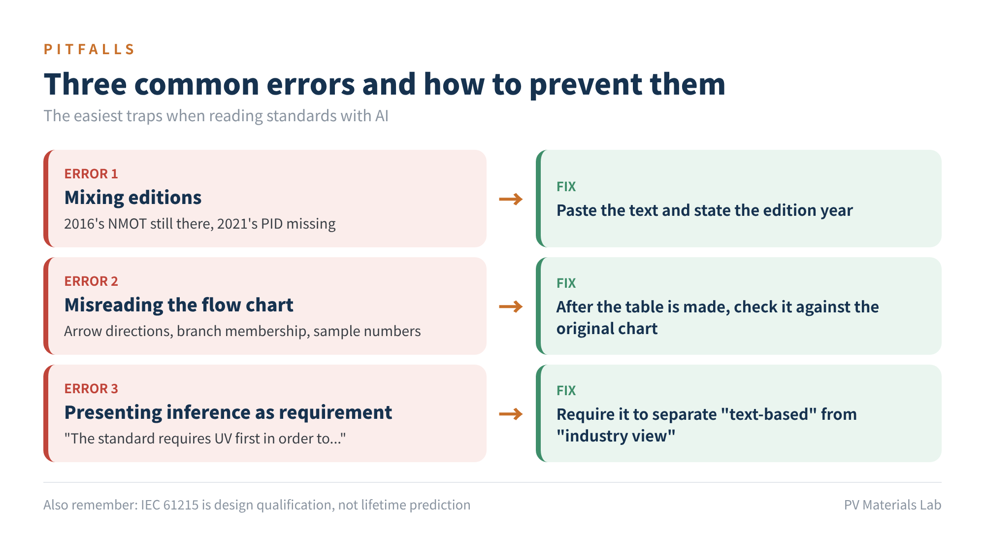
Figure 7 Three common errors and how to prevent them
- Mixing editions. Especially when no text is given: the 2016 NMOT is still there, and the 2021 PID test is missing. There is only one fix: paste the text and state the edition year.
- Misreading the flow chart. Arrow directions, branch membership and sample numbers are the hot spots. That is why, after Step 1 produces the table, you must check it against the original chart by hand.
- Presenting inference as requirement. Be wary of sentences like "the standard requires UV first in order to...". The standard only says what to do; the reasons are later interpretation.
08Final thoughts
There is one more thing AI often gets wrong, and every PV professional should remember it: IEC 61215 is design qualification, not lifetime prediction. Passing it shows the design has no obvious early-failure risks; it does not mean the module will run reliably outdoors for 25 years. That is exactly why the industry has various extended tests, and extended-stress tests such as IEC TS 63209.
Ten minutes buys you a map. Read the original with that map in hand and you will find the clauses go much faster.
Have the AI turn the chart into a table, then the table into plain words, then ask why; at every step, paste the text, state the edition, and keep "the text" separate from "inference".
Which chart or clause has tripped you up when reading standards? We would be glad to hear from you.
References
- IEC 61215-1:2021, Terrestrial photovoltaic (PV) modules – Design qualification and type approval – Part 1: Test requirements (technical changes as listed on the IEC Webstore)
- IEC 61215-2:2021, Terrestrial photovoltaic (PV) modules – Design qualification and type approval – Part 2: Test procedures
- IEC 61215-1-1:2021, Special requirements for testing of crystalline silicon photovoltaic (PV) modules
- IEC TS 62915:2023, Photovoltaic (PV) modules – Type approval, design and safety qualification – Retesting
- IEC TS 63209-1:2021, Photovoltaic modules – Extended-stress testing – Part 1: Modules
- BSI: Draft BS EN 61215-1 AMD1, March 2025
A PV R&D and technology team with 10+ years of experience | In-depth technical knowledge sharing
Materials · Reliability · Failure Analysis · Standards & Certification · Products · Processes
Exploring AI + PV; collaboration welcome
Disclaimer:
1. Original content reflects the authors' personal views only, is for reference only and does not constitute investment advice.
2. Reposted and cited content is credited to its source, out of respect for original work.
3. Some content was produced with AI assistance (chart generation, data retrieval, concept explanations, etc.); the core framework and key content were written by our technical team and reviewed by people.
4. If anything is inaccurate or infringes your rights, please leave a message or contact us and we will deal with it.