
Why Is Junction Box Creepage Distance Getting Harder in the 1500 V Era?
Introduction
Anyone who designs junction boxes, qualifies their materials or reviews certification reports has probably seen the "Clearances and creepage distances" measurement table. Clearance and creepage are always mentioned together, but they guard against two completely different failures. Here we take creepage distance apart: what it is, what determines it, where it applies in a junction box, and why in the 1500 V era it has increasingly become a hard constraint on housing materials and design.
01Creepage: the path that "creeps" along the surface
Start with the definitions. Creepage distance is the shortest distance between two conductive parts measured along the surface of insulating material; clearance is the shortest distance between them through air.
One "goes along the surface", the other "goes through the air". It may look like just a different way of measuring, but behind them are two different failure mechanisms:
- Clearance prevents air breakdown: impulse voltages from induced lightning or switching ionise the air and form an arc in an instant. It depends on the impulse withstand voltage and altitude, not on the insulating material itself.
- Creepage prevents tracking: dust and salt build up on the insulating surface and, with condensation or rain, form a weakly conductive film; under long-term voltage, tiny surface discharges gradually carbonise the polymer until they burn a conductive path (tracking). It depends on the long-term working voltage, how dirty the surface is, and the material's tracking resistance.
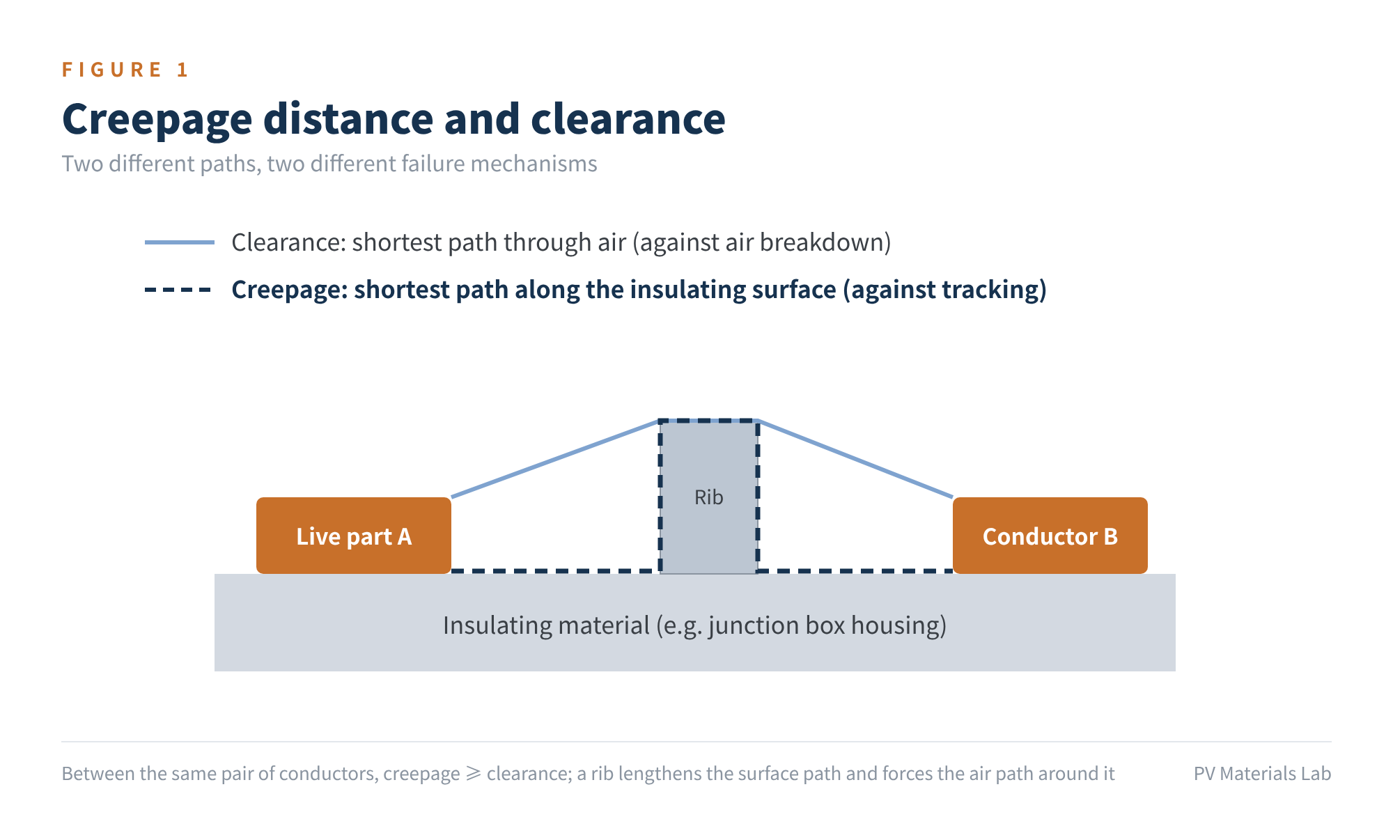
Figure 1 Creepage distance and clearance
An analogy: clearance is like "can you jump across the river in one step", while creepage is like "how far do you have to walk along the bank to get round". The first fears momentary high voltage; the second fears moisture and dirt that accumulate day after day. That is why, between the same pair of conductors, creepage is never less than clearance.
For PV modules, the second condition is the norm: modules serve outdoors for 25–30 years through damp heat, condensation, dust and salt mist, while the junction box carries the string's high DC voltage directly. That is why creepage distance weighs so heavily in junction boxes.
02Three variables that determine creepage distance
Creepage distance isn't an arbitrary fixed number. The junction box standard IEC 62790 applies to boxes rated up to 1500 V DC and designed for Class II (reinforced or double insulation), while the values themselves come from the basic insulation coordination standard IEC 60664-1, looked up from a table using three variables.
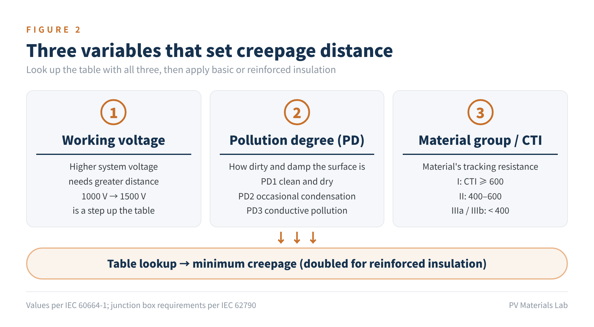
Figure 2 Three variables that set creepage distance
- Working voltage: the voltage applied long-term between two conductors; for DC, the DC value. The higher the voltage, the more easily surface discharges are sustained and the greater the distance required. Raising system voltage from 1000 V to 1500 V is a real step up in the table.
- Pollution degree (PD): describes the micro-environment of the insulating surface. PD1 means no pollution, or only dry non-conductive pollution; PD2 means normally only non-conductive pollution, occasionally made temporarily conductive by condensation; PD3 means conductive pollution, or dry pollution that becomes conductive due to condensation. Outdoor-exposed surfaces are usually treated as PD3; the inside of a well-sealed box is often assessed as PD2.
- Material group (CTI): CTI, the comparative tracking index, is the highest voltage a material surface can withstand without tracking under repeated drops of electrolyte. By CTI, materials fall into group I (≥ 600), II (400–600), IIIa (175–400) and IIIb (100–175). The higher the CTI, the smaller the distance needed under the same conditions.
Once the three variables are set, the type of insulation matters too: live parts to accessible surfaces require reinforced insulation, whose creepage distance is generally twice that for basic insulation. Taking the 1600 V row commonly used for 1500 V systems as an example, the values are roughly:
| Condition | Material group I CTI ≥ 600 | Material group II 400–600 | Material group III CTI < 400 |
|---|---|---|---|
| PD2 · basic insulation | 8.0 | 11 | 16 |
| PD2 · reinforced insulation | 16 | 22 | 32 |
| PD3 · basic insulation | 20 | 22 | 25 |
| PD3 · reinforced insulation | 40 | 44 | 50 |
Table 1 Minimum creepage distances at the 1600 V row, illustrative (unit: mm)
The most telling corner of this table is the bottom right: if the housing material has a low CTI and live parts are directly exposed to PD3 conditions, reinforced insulation requires creepage of several tens of millimetres, almost impossible in a palm-sized junction box.
Creepage distance = a table lookup of working voltage × pollution degree × material CTI, then basic or reinforced insulation. Voltage is set by the system; only the last two variables can be changed.
03Where to measure in a junction box
In an actual junction box, there are roughly three kinds of creepage path to watch:
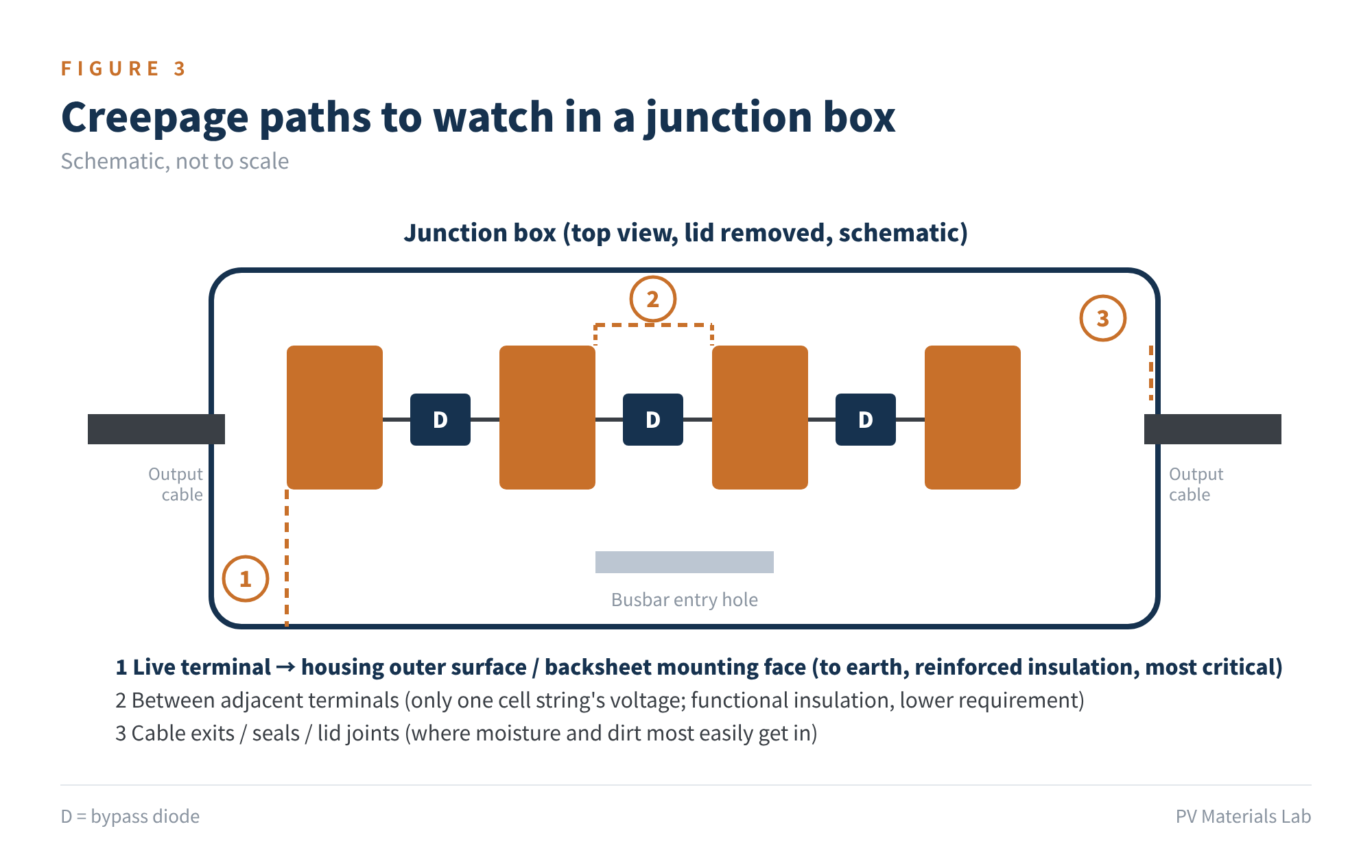
Figure 3 Creepage paths to watch in a junction box (schematic)
- Live parts to outer surfaces: paths from terminals and busbars to the housing's outer surface and the backsheet mounting face. This is insulation to earth, requires reinforced insulation, and is the most critical item and the one that most often constrains the design.
- Between terminals: adjacent terminals are separated only by the cell string protected by one bypass diode, so the voltage difference is usually just tens of volts. This is functional insulation, with much lower requirements.
- Cable exits, seals and lid joints: not necessarily the shortest path, but the route by which moisture and dirt enter the box, which determines what pollution degree the inside can actually maintain.
Measurement has its subtleties too. When a path meets a groove, not every groove "counts": if the groove is narrower than the specified value X, dirt bridges it and the path is taken straight across; only if the groove is wide enough do its walls and bottom count. X is also tied to pollution degree: about 0.25 mm for PD1, 1.0 mm for PD2 and 1.5 mm for PD3.
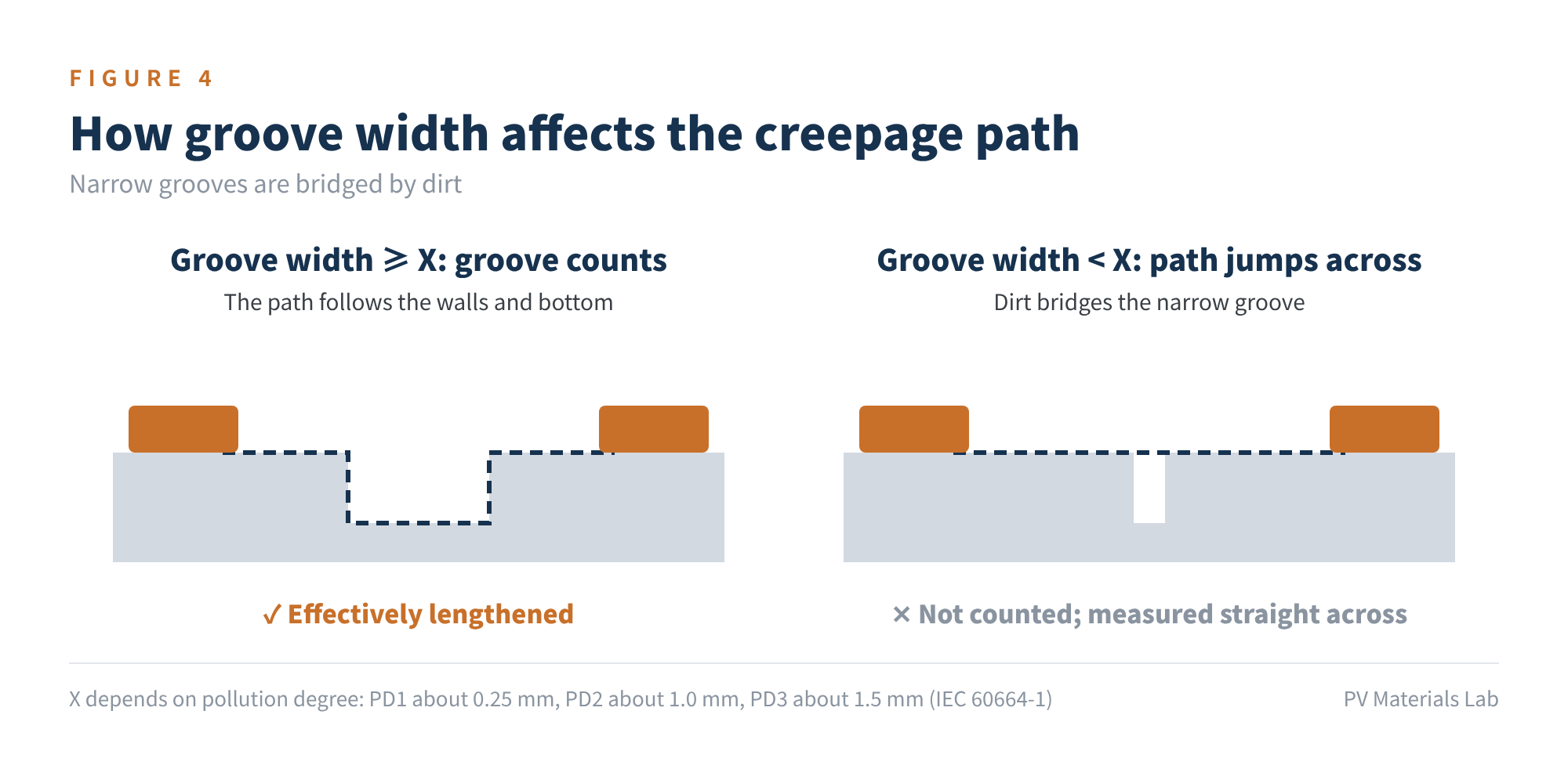
Figure 4 How groove width affects the creepage path
This also explains the ribs and grooves often seen inside junction boxes: they use geometry to "lengthen" the surface path within limited space.
04Why potting has become almost standard
Back to Table 1. Voltage is set by the system, and dimensions are constrained by space on the module back and by cost, which leaves materials and pollution degree as the levers. Mainstream junction boxes usually use both:
- Choose high-CTI materials: housings are commonly made of engineering plastics such as modified PPO and PC, and flame retardants, fillers and colourants in the formulation all affect CTI. The same grade in a different colour or batch can differ, so CTI must be verified separately during material qualification rather than taken from the datasheet. IEC 62790:2020 removed PTI from the material group categorisation procedure, so material group is determined by CTI; it also added requirements for RTE/RTI or TI (relative thermal endurance / temperature index) information for insulating parts.
- Pot or seal to lower the pollution degree: encapsulating live parts completely in silicone or similar potting compound keeps the surface away from air and moisture, lowering the pollution degree significantly, so the affected areas can be assessed as "solid insulation" rather than "surface paths". IEC 62790 requires that coating or potting used to lower the pollution degree meet the conditions of its Annex B, based on the principles of IEC 60664-3; the 2020 edition also added "distance through cemented joints" to Table 3, with corresponding test voltage requirements.
In other words, potting compound isn't just for waterproofing and heat conduction; in insulation coordination it plays the role of "rewriting the pollution degree". For that very reason, potting quality is itself part of insulation reliability: bubbles, shrinkage voids and debonding from the housing or terminals can all reopen a surface path locally.
A junction box's creepage distance isn't "measured into being"; it is "designed in" by structure, materials, sealing and potting together.
05Common misconceptions
- Misconception 1: creepage = clearance. They differ in measurement path, determining factors and the failures they address. Reports must satisfy each separately; meeting one doesn't mean meeting the other.
- Misconception 2: once it's potted, all is well. Potting only works if the layer is complete, well bonded and survives the ageing verification required by the standard. Debonding after damp heat or thermal cycling quietly eats the design margin.
- Misconception 3: a different colour or supplier doesn't matter. CTI is sensitive to formulation; when qualifying an alternative material, reconfirm CTI and material group rather than carrying over the existing certification conclusions.
- Misconception 4: relabel a 1000 V box and use it at 1500 V. Moving up a voltage row increases the minimum creepage distance; the existing design usually needs recalculating and, if necessary, recertifying.
06Final thoughts
Creepage distance is a classic "looks simple, constrained everywhere in practice" parameter. It ties together system voltage, outdoor environment, housing material and potting process: a change in any one of them can send a previously compliant design back into the "do we need to retest?" discussion.
Our advice to colleagues in module design and material qualification: when you see the voltage rating and certification conclusion on a junction box datasheet, ask one more question: under what pollution degree and what material group does it hold?
In this junction box series we will next look at test methods: which tests a junction box has to pass to be certified. What creepage issues have you run into when qualifying junction boxes? We would be glad to hear from you.
References
- IEC 62790:2020, Junction boxes for photovoltaic modules – Safety requirements and tests (edition 2, stability date 2030)
- IEC 60664-1:2020+AMD1:2025 CSV, Insulation coordination for equipment within low-voltage supply systems – Part 1: Principles, requirements and tests (edition 3.1, 2025-05-06)
- IEC 60664-3, Insulation coordination for equipment within low-voltage supply systems – Part 3: Use of coating, potting or moulding for protection against pollution
- IEC 61730-1, Photovoltaic (PV) module safety qualification – Part 1: Requirements for construction
- IEC 60112, Method for the determination of the proof and the comparative tracking indices of solid insulating materials
- TÜV Rheinland, Junction box: Overview of check routine according to IEC/EN 62790
A PV R&D and technology team with 10+ years of experience | In-depth technical knowledge sharing
Materials · Reliability · Failure Analysis · Standards & Certification · Products · Processes
Exploring AI + PV; collaboration welcome
Disclaimer:
1. Original content reflects the authors' personal views only, is for reference only and does not constitute investment advice.
2. Reposted and cited content is credited to its source, out of respect for original work.
3. Some content was produced with AI assistance (chart generation, data retrieval, concept explanations, etc.); the core framework and key content were written by our technical team and reviewed by people.
4. If anything is inaccurate or infringes your rights, please leave a message or contact us and we will deal with it.