
Offshore PV Goes Mainstream: Salt Mist, Sealing and Wave Splash, Three Trials Every Module Must Survive
In brief
Offshore PV is moving from demonstration projects to grid connection at scale, and modules now face not the "wind and sun" of land but long-term combined exposure to heavy salt mist, high humidity and dynamic wave-splash loads. We focus on the three parts most likely to fail: coatings and galvanic corrosion of aluminium frames, ageing of IP68 seals in junction boxes and connectors, and dynamic mechanical loads in the splash zone, and explain what parameters such as "salt mist level 8" and "wet leakage" really mean, so you can see which tests an offshore module actually has to pass.
Over the past two years, offshore PV in China has gone from "demonstration projects" to "grid connection at scale". The 400 MW pile-founded fixed project in Zhaoyuan, Shandong, is fully operational; the 1 GW project in Kenli, Dongying, Shandong, is fully grid-connected; and the 200 MW project in Ningde, Fujian, reached full grid connection in July this year. Once modules actually "go to sea", people start to find that offshore, the first things to fail are often not the cells but "peripheral parts" such as frames, junction boxes and connectors. In this article we look at the three tests offshore modules must pass: salt mist corrosion, wet leakage and sealing, and dynamic loads in the splash zone.
01From "demonstration" to "scale": how much harsher is offshore than land?
First, some recent milestones. On 27 May 2025, CGN's 400 MW Zhaoyuan project in Yantai reached full grid connection. It is China's first pile-founded fixed offshore PV project, located 2–6.2 km from shore in water 8.5–11 m deep, with more than 4,400 piles supporting about 760,000 n-type heterojunction bifacial glass-glass modules. In December 2025, the 1 GW Kenli offshore PV project in Dongying, Shandong, reached full grid connection: made up of 2,934 offshore PV platforms, it is China's first gigawatt-scale offshore PV project, with expected annual generation of about 1.78 TWh. On 31 July 2026, CGN's 200 MW "nuclear-plus-solar" project in Ningde reached full grid connection, using large-diameter high-performance concrete piles and expected to deliver about 300 GWh a year; in January the same year, the 220 kV export line of CNNC's 2 GW Tianwan tidal-flat PV demonstration project was completed. As scale grows, problems are magnified too: one reliability defect multiplied by hundreds of thousands of modules becomes a huge O&M bill.
The offshore environment is often summed up in the industry as "three highs and three strongs": high temperature, high humidity and high salt mist; strong wind, strong waves and heavy rain. For modules, these factors do not act alone but in relay: salt mist supplies the electrolyte, high humidity keeps surfaces wet for long periods, temperature speeds up chemical reactions, and wind and waves repeatedly flex materials that have already become brittle.
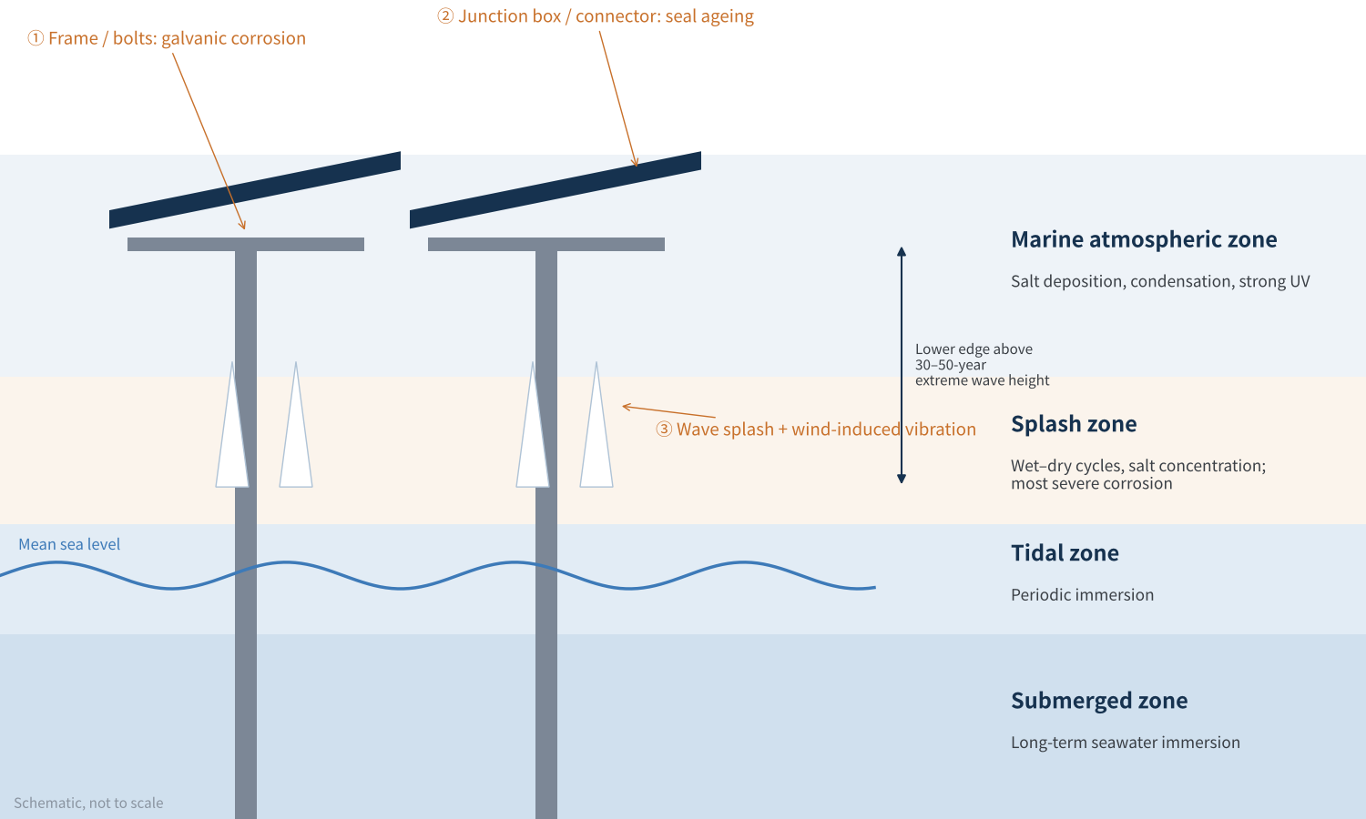
Figure 1 Offshore PV environmental zones and module risk points (schematic)
In terms of corrosion zones, offshore structures are generally divided into the marine atmospheric zone, splash zone, tidal zone and submerged zone. PV modules sit in the atmospheric zone, but in pile-founded fixed projects they are only a few metres above the water, and in strong winds and waves their lower edges come within reach of splash. The splash zone is recognised as the most corrosive: frequent wet–dry cycles, ample oxygen, and salt constantly replenished and concentrated.
The difficulty offshore is not "how big any single stress is" but "the long-term combination of salt, humidity, heat and force". A single salt mist certificate is nowhere near enough.
02What does "salt mist level 8" actually mean?
Many offshore module brochures claim to have "passed salt mist level 8". There is an easy misunderstanding here: "level 8" actually refers to "test method 8" in IEC 60068-2-52, not the "8th severity level".
The salt mist test standard for modules is IEC 61701, which does not set spray parameters itself but refers to IEC 60068-2-52. Older versions used "Severity 1–6", with Severity 6 being 8 cycles over 56 days, once called "the toughest in the industry". The 2017 revision of IEC 60068-2-52 replaced "severities" with "test methods" and added methods 7 and 8; IEC 61701:2020 was then updated, with Annex A giving guidance on which method to choose for different corrosive environments.
| Aspect | Method 6 (formerly Severity 6) | Method 7 / Method 8 |
|---|---|---|
| Cycle structure | Salt mist 2 h + damp heat 22 h, repeated 4 times, then 3 days in standard atmosphere (1 cycle = 7 days) | Salt mist 35 °C 2 h → dry 60 °C, ≤30% RH 4 h → humid 50 °C, ≥95% RH 2 h; about 8 h per cycle |
| Duration | 8 cycles, 56 days in total | 3–180 cycles (about 1–60 days) |
| Character | Long damp-heat periods, mainly "soaking" | Frequent wet–dry cycles, closer to the real marine atmosphere |
| Salt solution | Neutral NaCl solution | Method 7 neutral; method 8 acidified salt solution with pH adjusted using glacial acetic acid |
| Corrosivity category | C5 (highly corrosive marine) | CX (extreme offshore) |
Table 1 IEC 60068-2-52 method 6 vs methods 7/8
The key change in methods 7 and 8 is the addition of a drying phase. Don't underestimate it: as the salt solution dries, it concentrates and crystallises, then redissolves when wetted again, so local chloride concentrations become far higher than in the original solution. This is exactly what happens at sea: drying in the daytime sun, condensation at night, and another layer of salt from the spray. Method 8 adds an acidified solution on top, further accelerating attack on metal coatings and sealing interfaces.
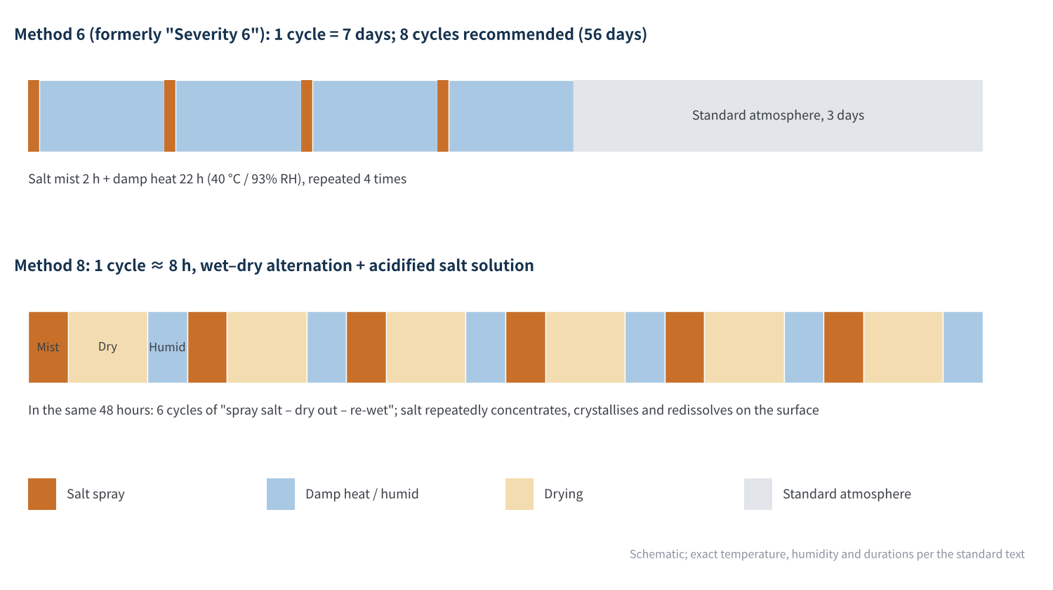
Figure 2 Cycle structure of salt mist test methods 6 and 8 (schematic)
Following the approach of IEC 61701:2020 Annex A, locations within 2 km of the sea with a high share of wetness time correspond to C5, while offshore sites correspond to CX, for which methods 7 or 8 are recommended. In other words, "salt mist level 8" is a threshold for offshore projects, not a bonus.
- Check the method number, not just the word "passed": method 1 and method 8 are tests of different orders of magnitude.
- Check the sample configuration: results differ greatly depending on whether the frame, junction box, connectors and mounting bolts were tested together.
- Check the pass criteria: beyond power loss, look at post-test wet leakage, insulation withstand and visual corrosion.
- Check the number of cycles: methods 7/8 range from 3 to 180 cycles, so for anything called "method 8", ask how many cycles were run.
03Aluminium frames: the coating holds, but the bolt holes go first
Module frames are generally 6063 aluminium alloy, protected by anodising or coatings. An anodic oxide film is an excellent barrier in itself, but in high-chloride environments its thickness and sealing quality directly determine its life. Offshore modules typically require an oxide thickness of class AA15 (≥15 μm), thicker than for standard onshore modules.
The real weak point, however, is often not the main surface of the frame but the mounting holes and bolted joints. Aluminium frames, steel bolts and galvanised steel structures sit side by side, and a film of sea salt provides a ready-made electrolyte, forming a galvanic cell: aluminium, with the more negative potential, becomes the anode and corrodes preferentially. The edges of mounting holes are machined surfaces with incomplete oxide, and once crushed by bolts they become the starting point of corrosion.
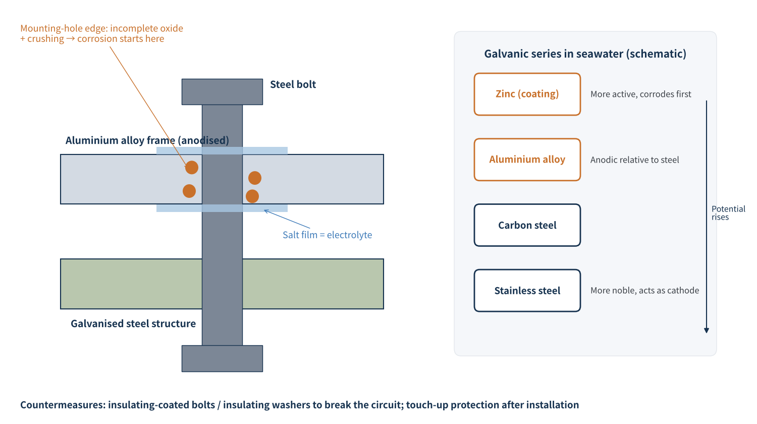
Figure 3 Galvanic corrosion at the aluminium frame / steel bolt / galvanised structure joint
One manufacturer ran cyclic salt mist method 8 tests with bolts installed and found embrittlement near the mounting holes and reduced mounting strength; the same phenomenon appeared at a fishery-solar project after eight years of operation. This shows that lab results and field behaviour match.
- Frame side: increase oxide thickness and sealing quality; deburr mounting holes and add secondary protection.
- Fastener side: use bolts with insulating coatings such as Dacromet, or add insulating washers, to break the galvanic circuit.
- After installation: touch up paint or apply protective sealant at joints so that cut edges and crushed areas are not left exposed.
Frame problems on offshore modules are essentially "system problems": however good the frame, if the bolts and structure don't keep up, corrosion still starts at the joints.
04Junction boxes and connectors: IP68 does not mean "never lets water in"
The junction box and connectors are the module's only "electrical exit" and the most failure-prone parts offshore. Research reviewing failures in marine environments notes that metal parts such as connectors and cables are the first to corrode if not properly sealed. The problem is that many people treat "IP68" as foolproof.
IP68 is a protection rating for a new product as delivered, testing that no water enters during short-term immersion. But offshore modules face 25–30 years of service, and the most insidious threat is the "breathing effect": during the day the junction box heats up and its internal pressure rises; at night it cools and contracts, creating negative pressure that gradually "draws in" humid, salty outside air. Day after day, under UV, ozone, salt and thermal cycling, seals harden and take a compression set, sealing force falls, and more and more moisture is drawn in.
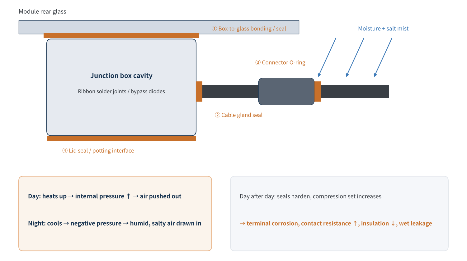
Figure 4 Main water ingress paths and the "breathing effect" in junction boxes and connectors (schematic)
What happens once moisture gets in? First, metal terminals and busbars corrode, contact resistance rises, causing local heating and, in severe cases, burn-out. Second, insulation degrades, leakage current to ground increases, and inverter insulation-resistance alarms or even shutdowns are triggered. That is why, besides salt mist, offshore modules need particular attention to wet leakage testing.
The wet leakage current test in IEC 61215 (MQT 15) immerses the module in a conductive solution and measures insulation resistance at system voltage; for modules larger than 0.1 m², the product of insulation resistance and area must be at least 40 MΩ·m². For offshore modules, "wet leakage after ageing" is more meaningful: can insulation still hold after salt mist, damp heat and immersion cycling? Some manufacturers have introduced tests combining pressurised immersion with thermal cycling to assess wet leakage and insulation after soaking in seawater.
- Connectors: the body should meet IP68 and salt mist method 8, with an added protective cover for "double protection".
- Dust caps: unmated connectors must wear dust caps during installation to keep morning and evening condensation out of the mating area.
- Cables: use double-insulated waterproof cables of matched length, so they are not repeatedly tugged as they sway with the waves.
- Same-model mating: mixing connectors from different brands is an old problem onshore and is magnified many times offshore.
IP68 answers "does water get in when it is new"; offshore, the real question is "is it still sealed when it is old". Seal materials and long-term ageing data matter more than an IP rating.
05Dynamic loads in the splash zone: "chronic fatigue" beyond salt mist
The third trial is mechanical load. Offshore winds are strong and gusts are dynamic; in big waves, spray and moisture also strike the lower edges of modules in pile-founded fixed projects. Even without direct impact, continuous wind-induced vibration subjects modules, frames and bolts to thousands upon thousands of "small flexes".
The standard dynamic mechanical load test (DML) is usually ±1,000 Pa for 1,000 cycles, to check whether cell cracks propagate during cycling. Offshore projects commonly tighten this: one manufacturer cites enhanced conditions of 1,500 Pa for 20,000 cycles, plus 60 m/s wind-tunnel testing and 2.3 million vibration cycles. With cycle counts raised by more than an order of magnitude, the test is no longer just about cells but about the fatigue life of frame corner keys, adhesive layers and bolt preload.
Even more worrying is the coupling of corrosion and fatigue: mounting holes weakened by salt mist, bolts loosened by vibration and cable terminals tugged back and forth all accelerate one another. Once a bolt loosens, the module vibrates more, wear at the joint damages the oxide film, and corrosion speeds up further. That is why offshore projects commonly recommend anti-loosening bolts and more frequent inspections after typhoons and storm surges.
- Mounting height: in pile-founded fixed projects, the lower edge of the modules should be above the local 30–50-year extreme wave height, avoiding direct splash at source.
- Frame structure: increase wall thickness appropriately and optimise clamp and bolt positions to shorten lever arms and improve resistance to wind uplift.
- Anti-loosening design: use anti-loosening bolts and install them to the torque specified in the manual, so vibration does not erode the torque.
Offshore module reliability is not about passing any single test, but about whether the module still stands after salt mist, wet leakage and dynamic loads are applied in sequence.
06Final thoughts
Large-scale grid connection of offshore PV is a "stress test" for the PV industry. Design margins that are "good enough" onshore may fall just short offshore. Our view: offshore modules compete not on individual specs but on system durability: frames and bolts must be designed together, junction boxes and connectors judged on post-ageing data, and load tests run in sequence with corrosion tests.
For owners and design institutes, it is worth asking three questions during module selection: which salt mist method was used, for how many cycles, and with or without mounting hardware; whether wet leakage data are for new or aged modules; and how many cycles of dynamic load were applied. Once these three questions are answered, you will really know where an offshore module stands on its "trials".
We will continue with topics such as junction box sealing materials and connector failure analysis. What problems have you met in offshore or coastal projects? We would be glad to hear from you.
References
- The Paper. Offshore PV scale-up accelerates: CGN Yantai Zhaoyuan 400 MW project connected to the grid, 2025-05-27
- MyDrivers. World's largest: China's first gigawatt-scale offshore PV project fully grid-connected (Kenli, Dongying, Shandong), 2025-12-27
- Science and Technology Daily. CGN Ningde 200 MW offshore PV project fully grid-connected, 2026-07-31
- Xinhua. Export line of China's largest offshore PV project completed (CNNC Tianwan 2 GW tidal-flat PV demonstration project), 2026-01-29
- IEC 61701:2020 Photovoltaic (PV) modules – Salt mist corrosion testing
- IEC 60068-2-52:2017 Environmental testing – Test Kb: Salt mist, cyclic (sodium chloride solution); Ascott Analytical. IEC 60068-2-52 Test Methodology
- IEC 61215-2 Terrestrial PV modules – Design qualification and type approval – Part 2: Test procedures (MQT 15 / MQT 20)
- Trina Solar. Offshore PV module white paper (20260205V1)
- He Dajuan, Han Xue, Yang Xueshan, et al. Design and reliability study of offshore PV modules. Acta Energiae Solaris Sinica, 2025, 46(9): 564–570
- Astronergy. ASTRO N offshore module and PIT test introduction, 2025-11
A PV R&D and technology team with 10+ years of experience | In-depth technical knowledge sharing
Materials · Reliability · Failure Analysis · Standards & Certification · Products · Processes
Exploring AI + PV; collaboration welcome
Disclaimer:
1. Original content reflects the authors' personal views only, is for reference only and does not constitute investment advice.
2. Reposted and cited content is credited to its source, out of respect for original work.
3. Some content was produced with AI assistance (chart generation, data retrieval, concept explanations, etc.); the core framework and key content were written by our technical team and reviewed by people.
4. If anything is inaccurate or infringes your rights, please leave a message or contact us and we will deal with it.