
How UV Light "Steals" Module Lifetime: UVID Explained
In brief
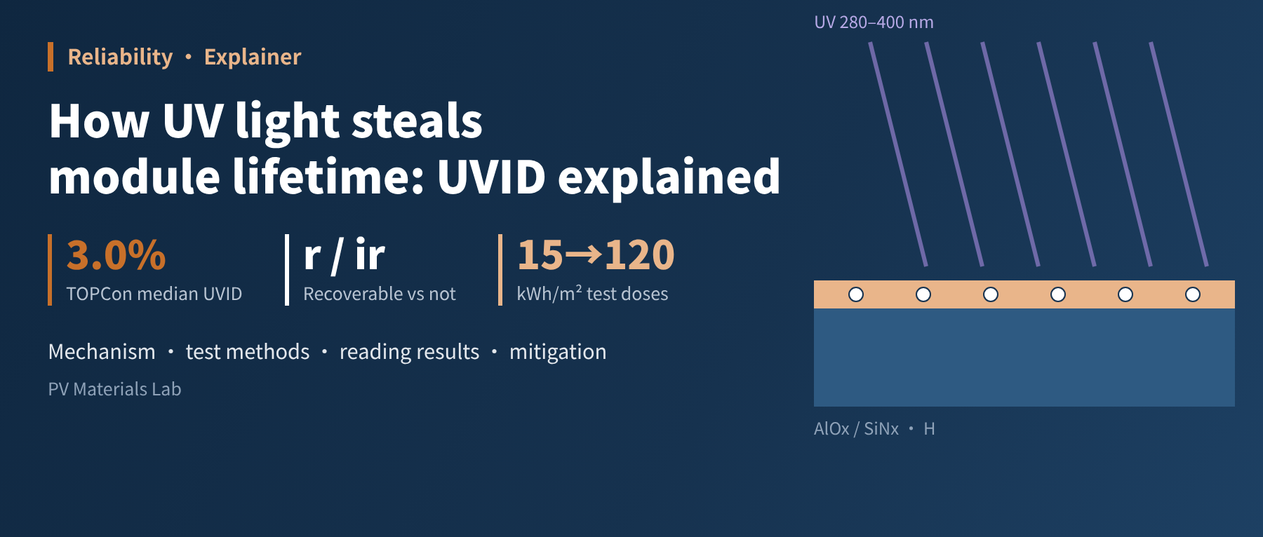
With n-type modules now mainstream, ultraviolet-induced degradation (UVID) has turned from an "old problem" back into a reliability focus. We cover where UV comes from, how it dismantles the front passivation of the cell, why TOPCon is more sensitive, how the industry tests it, how to read the results, and mitigation at cell, material and module level. Key conclusion: UVID is a real problem, but a sizeable part of lab figures is recoverable metastability, and separating "recoverable" from "non-recoverable" matters more than fixating on a single degradation value.
Over the past two years, one term has appeared in almost every third-party reliability report: UVID. In the PERC era, UV was mainly treated as an "external cause" of encapsulant yellowing and backsheet chalking; in the n-type era, it targets the cell itself. Some modules lose more than ten percentage points in the lab while others barely lose anything; the same module loses more after a few days in the dark, then recovers after a few days in the sun. In this article we walk through UVID from start to finish.
01UV light: a small share, a big punch
Ultraviolet light at 280–400 nm makes up only about 4–5% of the energy in sunlight reaching the ground, but it carries the highest-energy photons. It is usually divided into two bands: UVA at 320–400 nm accounts for most ground-level UV, while UVB at 280–320 nm is scarce but has higher energy per photon and greater destructive power.
For a module, UV must first pass through the glass and the front encapsulant before reaching the cell. So "how much UV the cell receives" depends first on the transmission of the front materials. EVA as traditionally used contains UV absorbers that cut off much of the light below 380 nm; but to gain yield, the industry has increasingly adopted UV-transmitting encapsulants that let this light through to be converted into current. The gain is a little extra short-circuit current; the cost is more high-energy photons reaching the cell surface.
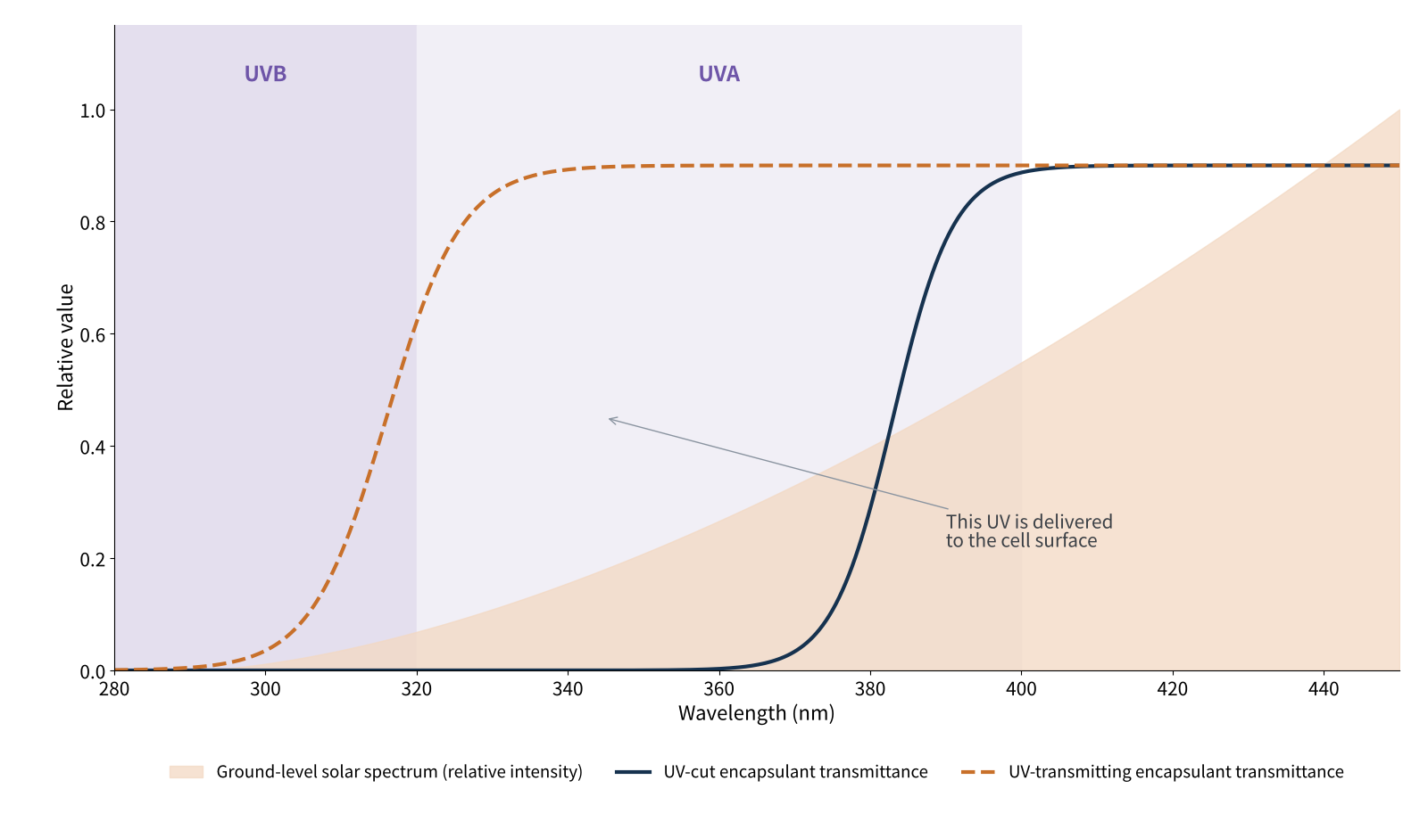
Figure 1 Ground-level solar UV and transmission of two types of encapsulant (schematic)
Third-party lab Kiwa PVEL has stated clearly that TOPCon and HJT sensitivity to UVID is especially pronounced when combined with UV-transmitting encapsulants; its presentation at EU PVSEC 2026 in September added that encapsulants with UV cut-offs below 300 nm were associated with higher degradation. In other words, UVID is determined jointly by cell structure and encapsulation scheme; looking at the cell or the encapsulant alone gives an incomplete picture.
02Mechanism: how UV "dismantles" the passivation layer
To understand UVID, look at the outermost few dozen nanometres of the cell. In a mainstream TOPCon cell, the front is a p+ boron emitter, topped by a few nanometres of aluminium oxide (AlOx) and about 75 nm of silicon nitride (SiNx). AlOx provides chemical and field-effect passivation; SiNx is both the anti-reflection coating and a "hydrogen reservoir": hydrogen released during firing saturates dangling bonds at the silicon surface.
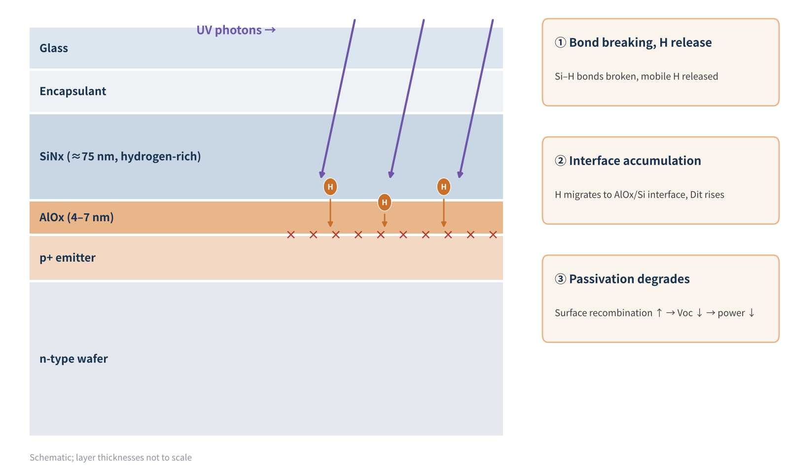
Figure 2 UVID mechanism in the TOPCon front passivation stack (schematic)
Research over the past two years by several groups (UNSW, Yangzhou University with JinkoSolar, Trina Solar and others) has described the process increasingly clearly. It can be summarised in three steps:
- Bond breaking and hydrogen release: high-energy UV photons break Si–H bonds in the SiNx, releasing mobile hydrogen.
- Hydrogen accumulation at the interface: free hydrogen migrates to and accumulates at the AlOx/Si interface, raising the interface defect density (Dit) and degrading chemical passivation.
- Charge trapping and structural rearrangement: UV also changes the fixed charge in the dielectric layers, weakening field-effect passivation; some studies have also observed irreversible structural rearrangement in the dielectrics.
Once passivation degrades, surface recombination rises. Open-circuit voltage (Voc) falls first, followed by fill factor and power. Notably, the process occurs mainly at the front: UNSW research found that the thicker doped polysilicon at the rear absorbs photons below 370 nm, acting as a natural "shield".
HJT follows a similar path with a different "protagonist": its UVID is thought to stem mainly from hydrogen-related effects and dopant deactivation in the front i/n amorphous silicon layers, and Kiwa PVEL's data also show HJT losses dominated by Isc and FF, with slower recovery. PERC also suffers UVID, but its different front structure and process window give it a different sensitivity.
UVID is essentially a story about hydrogen: UV light drives out the hydrogen that was quietly passivating defects and sends it where it should not be.
03Why n-type modules have been "singled out"
In the PERC era, UV issues faded from third-party testing for a while, because most modules performed well and attention shifted to more pressing problems such as LID and PID. As n-type cells became mainstream, UVID was brought back into extended reliability testing. Kiwa PVEL formally added a UVID sequence when it updated its Product Qualification Program (PQP) in November 2023.
There are three reasons: first, the thin front stacks of n-type cells are more "delicate" and more sensitive to interface conditions; second, encapsulants have broadly moved towards high UV transmission; third, TOPCon's high efficiency and Voc mean that even a slight increase in surface recombination is easily amplified into losses.
What do the data say? In Kiwa PVEL's 2024 Scorecard, power loss after 120 kWh/m² of UV ranged from 0.6% to 16.6% across BOMs, a very wide spread, yet four TOPCon BOMs lost less than 1%, showing that UV-stable TOPCon is entirely achievable. By the 2026 Scorecard, the median UVID loss of TOPCon BOMs had fallen from 4.2% the previous year to 3.0%, and the share of BOMs failing UVID from 6% to 3%, with 91 BOMs from 19 manufacturers named UVID Top Performers.
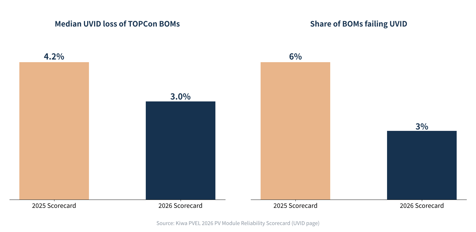
Figure 3 Change in UVID loss of TOPCon modules in Kiwa PVEL Scorecards
At EU PVSEC 2026 in September, Kiwa PVEL and the Netherlands' NLR summarised 370 modules tested in 2024–2026 (78% TOPCon): after UV120, TOPCon lost 0.4–16.6% with a median of 3.0%, HJT (limited sample) 1.5–8.6% with a median of 5.2%, and PERC a median of 2.1%. Their conclusion: UVID stability is improving, but it is not solved yet.
There are dissenting voices too. A joint study by Yangzhou University, Changzhou University and JinkoSolar argues that an optimised SiNx/AlOx stack can make TOPCon cells more UV-resistant than PERC. This does not contradict third-party findings that "TOPCon is more sensitive": the former is a cell-level comparison with optimised processes, the latter a sample of commercial modules on the market. The difference lies not in the technology route itself but in each manufacturer's process and BOM.
04How it is tested: the different "exams" at a glance
UVID test methods are not yet unified, and UV doses differ by up to a factor of eight between standards and organisations.
| Test method | UV dose | Role |
|---|---|---|
| IEC 61215-2 MQT 10 | 15 kWh/m² (60 °C) | Preconditioning before damp heat / humidity freeze |
| IEC 61730 MST 54 | 60 kWh/m² | Safety certification, focused on materials |
| Kiwa PVEL UVID (PQP V12) | Continuous 120 kWh/m² (metal halide; 75 kWh/m² with UV fluorescent lamps), optional extension to 360 kWh/m² | Extended reliability, focused on front-side power loss |
| IEC TS 63624-1 (at final ballot) | Higher dose + light-soak recovery | Dedicated UVID assessment for crystalline silicon modules |
Table 1 Comparison of the main UV test methods
The problem lies in that figure of 15 kWh/m². An NREL study of one power plant found that the MQT 10 dose corresponds to only about 2–3 months outdoors (about 1.8 months at that plant), while about 67.5 kWh/m² of UV exposure was needed before measurable power loss appeared. In other words, passing IEC certification does not mean passing the UVID test.
The NREL study also had an easily overlooked finding: after UV exposure followed by 1,000 hours of damp heat (85 °C / 85% RH), the series resistance of UV-exposed cells rose sharply, linked to a lack of zinc in the metallisation paste (severe series resistance degradation was also seen in samples whose paste did contain zinc). This suggests the combined effect of UV and damp heat may deserve more attention than either stress alone.
On the standards side, IEC TS 63624-1 entered stage 50.20 (proof sent to the secretariat or final ballot initiated) on 2 October 2026, with the next stage planned for late November. It is set to become the first international test specification dedicated to UVID in crystalline silicon modules.
05The key step: how much of the measured loss is real?
This has been the most important turn in the UVID debate over the past year. Fraunhofer ISE found that commercial TOPCon modules show clear metastability after UV exposure: stored in the dark after UV, their efficiency keeps falling; put back in the sun, it recovers significantly. Measuring "straight after UV" or "after dark storage", as is common practice, clearly overestimates the degradation.
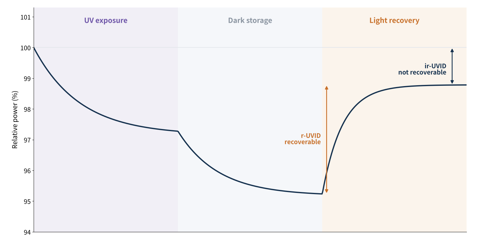
Figure 4 Metastable UVID behaviour: UV exposure → dark storage → light recovery (schematic)
Some key data: after 60 kWh/m² of UV (roughly one year's UV in Germany) followed by sunlight stabilisation, Fraunhofer found some modules with almost no degradation but others still losing up to about 5% after recovery. Kiwa PVEL observed that UVID-sensitive TOPCon modules can degrade by about 1% per day in dark storage after testing. According to a Fraunhofer report summarised by TaiyangNews, even without UV exposure, factory-new TOPCon modules showed dark-storage degradation of about 0.1% per month in the lab, which recovered with light soaking after reaching about 0.6%. A new paper by a Fraunhofer team in Solar RRL in October further found that UVID is almost completely suppressed under simultaneous UV and visible light (at open circuit), and that higher temperature reduces net degradation.
On this basis, a Trina Solar research team proposed splitting UVID into two types, aligned with the recovery procedure in IEC TS 63624-1:
- r-UVID (recoverable): mainly due to hydrogen redistribution and changes in interface charge trapping; it can be recovered by light soaking or thermal annealing, recovers dynamically under daily sunlight outdoors, and does not affect actual yield.
- ir-UVID (irreversible): the loss that remains after standardised light-soak recovery; this is what truly eats into yield and needs to be included in warranty and financing assessments.
But "recoverable" does not mean "no problem outdoors". Modules exposed outdoors for one year by Kiwa PVEL in Davis, California, showed a median loss of about 2% and a maximum of 8%, with EL patterns matching indoor results, and most of the bills of materials would not meet a "<1% first-year degradation" warranty. NREL research published in February also measured 2.3–3.2% of non-recoverable loss after a UV dose equivalent to about one year outdoors. Kiwa PVEL stresses that light soaking recovers the dark-storage part, while the UV-induced damage itself is not recovered.
When reading a UVID report, first ask: is this figure "after recovery"? A degradation value without light stabilisation can only serve as an upper bound; what remains after recovery is the real risk.
06Mitigation: action at cell, material and module level
The good news is that UVID can be engineered away, as the improvement in the 2026 Scorecard shows; Kiwa PVEL has also reported a TOPCon BOM that improved from 6.5% to 1.3% degradation on retest. Drawing on recent research, the main levers are:
- AlOx thickness and process: UNSW research shows that 7 nm of AlOx is significantly more UV-resistant than 4 nm because it better blocks hydrogen migration; PEALD is usually better than conventional PECVD. But too thick a layer causes blistering and higher tunnelling resistance, so a balance is needed.
- Capping layer and refractive index: replacing or adjusting SiNx with SiON can stabilise hydrogen and improve chemical passivation; raising the SiNx refractive index somewhat absorbs more UV and protects the interface below, at the cost of a little optical loss.
- Hydrogen management: optimise deposition temperature, gas ratios, firing profiles and annealing conditions so hydrogen "stays where it belongs".
- Encapsulant selection: where cell UV stability is insufficient, a UV cut-off in the front encapsulant remains the most direct safeguard; once cells are stable enough, high-transmission encapsulants can capture the extra gain. UV down-converting encapsulants are currently used mainly in HJT, and their long-term reliability still needs verification.
- Validation: when selecting modules, require high-dose UV testing plus standardised light-soak recovery, and pay attention to combined UV and damp-heat sequences; sensitivity varies between cells in the same module, so sampling should cover multiple cells and batches.
Our advice to buyers and plant owners: don't just check "does it pass IEC"; look at the post-recovery results of high-dose UVID testing, and include the encapsulant model in the locked BOM: the same cell with a different encapsulant can perform completely differently on UVID.
07Final thoughts
From PERC to TOPCon and HJT, every leap in cell efficiency brings new reliability challenges. UVID is the challenge of the n-type era: it is real and is gradually being solved; it can be exaggerated by test methods, but it must not be dismissed because of that.
For the industry, the next key step is to separate "recoverable" from "non-recoverable", standardise testing and write it into contracts. Once IEC TS 63624-1 is formally published, UVID may, like PID before it, move from a "risk item" to a "routine test item". Until then, asking "what is it after recovery?" will help you avoid many pitfalls.
What problems have you encountered in UVID testing or module selection? We would be glad to hear from you.
References
- Kiwa PVEL. 2026 PV Module Reliability Scorecard – Ultraviolet Induced Degradation.
- Kiwa PVEL. 2024 PV Module Reliability Scorecard – UVID.
- Kiwa PVEL & NLR. UV-Induced Degradation in TOPCon and Other Modules. EU PVSEC 2026, 2026-09-14.
- Sinha A, Jaubert J-N, Karin T. UV-Induced Degradation in N-Type Modules: Exploring Metastability and Recovery Pathways. IEEE PVSC, 2025.
- Kiwa PVEL. UV-Induced Degradation (UVID test description).
- Fraunhofer ISE. Fraunhofer ISE evaluates common UV tests for TOPCon modules for practical relevance. Press release, 2025-04-10.
- TaiyangNews. Understanding UVID, Glass Breakage, and Metastability in Modern TOPCon Modules (Fraunhofer ISE report).
- pv magazine USA. NREL researchers warn of unexpectedly high UV-induced degradation in n-type solar modules, 2025-09-17; pv magazine USA. NREL researchers quantify UV-induced degradation levels in TOPCon solar cells, 2026-02-18.
- pv magazine. UNSW research offers guidance for more robust TOPCon solar cells (AlOx thickness and hydrogen transport).
- pv magazine Australia. Research warns of UV-induced degradation in TOPCon solar cells from invisible light, 2025-08-12.
- pv magazine. Trina Solar researchers propose new classification of ultraviolet-induced degradation in TOPCon solar cells, 2026-10-14; original paper: Solar Energy Materials and Solar Cells.
- pv magazine. New research uncovers interface-level physical mechanisms driving UV degradation in TOPCon solar cells, 2026-05-08.
- Khan et al. Charge Trapping, Hydrogen Accumulation, and Structural Rearrangement: A Complete Model for UVID in TOPCon Devices. Sol. Energy Mater. Sol. Cells 298 (2026) 114149.
- Messmer P., et al. Solar RRL, 2026. DOI: 10.1002/solr.70516.
- TaiyangNews. UV-Induced Degradation in SHJ Cells.
- IEC 61215-2:2021 MQT 10; IEC 61730 MST 54 (UV preconditioning requirements); IEC TS 63624-1 project information (ISS project page).
A PV R&D and technology team with 10+ years of experience | In-depth technical knowledge sharing
Materials · Reliability · Failure Analysis · Standards & Certification · Products · Processes
Exploring AI + PV; collaboration welcome
Disclaimer:
1. Original content reflects the authors' personal views only, is for reference only and does not constitute investment advice.
2. Reposted and cited content is credited to its source, out of respect for original work.
3. Some content was produced with AI assistance (chart generation, data retrieval, concept explanations, etc.); the core framework and key content were written by our technical team and reviewed by people.
4. If anything is inaccurate or infringes your rights, please leave a message or contact us and we will deal with it.