
Ribbon and Module Reliability: What Are Reliability Tests Really Testing in the Ribbon?
In brief
Much of what module reliability tests such as TC, DH and dynamic mechanical load examine is the ribbon and its solder joints. Using IEC 61215 as a reference, this article sets out what each test stresses in the ribbon, uses estimates to show why TC200 accelerates solder joint fatigue, discusses how ribbon must be matched to thinner cells, cell metallisation and encapsulants, and closes with ways to improve module reliability through ribbon selection and design.
In the previous article we followed the timeline of ribbon-related failures. This article widens the view to the whole module: in certification and reliability testing, what exactly is being "tested" in the ribbon? And how should ribbon "work with" the cell, encapsulant and cell metallisation so the module lasts twenty or thirty years? Our view in one sentence: ribbon is not an isolated material; its reliability depends on how well it matches the whole module system.
01What reliability tests examine in the ribbon
Design qualification and type approval of modules are based mainly on the IEC 61215 series. Several of its tests focus squarely on ribbon and solder joints:
| Test | Typical conditions | What it stresses in the ribbon |
|---|---|---|
| Thermal cycling TC200 | −40 °C to 85 °C, 200 cycles, current applied while heating | Joint fatigue, bending fatigue of interconnect ribbon |
| Damp heat DH1000 | 85 °C, 85% RH, 1,000 h | Corrosion of joints and metallisation, compatibility with encapsulant |
| Humidity freeze HF10 | 85 °C/85% RH, then down to −40 °C, 10 cycles | Interface adhesion, moisture and freezing stress |
| Dynamic mechanical load DML | ±1,000 Pa, 1,000 cycles | Interconnect ribbon fatigue, crack propagation |
| Static mechanical load | Usually from 2,400 Pa, higher per design load | Cracks, loads on joints |
| Hot-spot endurance | One cell shaded, local heating | Heat resistance of joints and ribbon |
Table 1 Main IEC 61215 tests and what they stress in the ribbon
One easily overlooked detail: under IEC 61215-2:2021, a current equal to the maximum power point current is passed through the module during the heating part of TC. Current flowing through ribbon and joints produces Joule heating, and the higher a joint's resistance, the more heat it generates, making TC more sensitive to cold joints and joint defects.
Beyond international certification, more and more module makers and plant owners use tougher extended tests, such as TC600, DH2000–3000 and the combined sequences in IEC TS 63209-1. To a large extent, these extended tests "amplify" the long-term problems of ribbon and joints.
The latest third-party data bear this out. According to pv magazine, in RETC's 2026 PV Module Index the share of BOMs failing thermal cycling rose from 2% the year before to 5%, and damp heat failures (more than 5% power loss) rose from 6% to 11%. In the Kiwa PVEL 2026 Scorecard, a record 87% of participating manufacturers had at least one failure, and the report lists cost-driven changes such as thinner encapsulants and zero-busbar designs among those linked to higher degradation or failure risk.
02TC: the ribbon's main exam
Of all the tests, thermal cycling examines ribbon most directly. We calculated the copper–silicon thermal mismatch strain in the previous two articles; here we take a different angle and compare the strain amplitude outdoors and in TC:
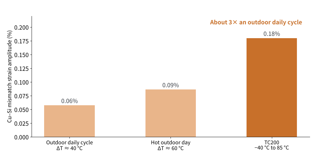
Figure 1 Copper–silicon thermal mismatch strain amplitude: outdoor daily cycles vs. TC200 (estimate)
The daily temperature swing outdoors is typically 40–50 °C, giving a thermal mismatch strain amplitude of about 0.06%–0.09%; TC200 spans 125 °C, giving about 0.18%, roughly 2–3 times an outdoor daily cycle. Metal fatigue life is very sensitive to strain amplitude: a few times more strain amplitude can cut fatigue life by an order of magnitude or more. That is why a mere 200 cycles can, to some extent, simulate years of joint fatigue outdoors.
But TC200 mainly reveals "early defects": cold joints, poor soldering quality, ribbon that is too hard, stress concentration in the cell gap and so on. To assess long-term joint life, look at degradation trends over longer cycles such as TC400 and TC600, focusing not just on "pass or fail" but on how power loss and series resistance change with the number of cycles.
TC accelerates joint fatigue with a strain amplitude about 2–3 times that outdoors, plus current-induced heating, making it the ribbon's main exam. Read TC results as trends, not just pass/fail.
03Mechanical load and DH: two more exams
Mechanical load tests the interconnect ribbon and cracks. Wind and snow loads bend the module, and the interconnect ribbon is repeatedly stretched and bent; at the same time, the ribbon end is a stress concentration point on the cell, and existing micro-cracks grow along the ribbon under load. Running TC and humidity freeze after dynamic mechanical load is a common combined sequence in the industry, designed to examine the combined effect of "cracks plus joint fatigue". In the Kiwa PVEL 2026 Scorecard, 26% of BOMs in the mechanical stress sequence (MSS) had at least one module break, and module breakage was the top failure mode this year.
Damp heat tests the compatibility of the material system. Ribbon coating, flux residue, encapsulant and cell silver paste spend a long time together at 85 °C and 85% humidity, and a mismatch in any one of them can cause corrosion, yellowing or rising contact resistance. So damp heat results often reflect not the quality of the ribbon alone but the performance of the whole BOM combination.
04Three matches: ribbon is not an isolated material
With the tests understood, let's look at what ribbon needs to "match" in module design. We see three key matches.
First, matching thinner cells. As cells get thinner, they can withstand less stress. Ribbon yields during cooling and thermal cycling, so the maximum force it can "pull" on the cell is roughly the total copper cross-section of the ribbons times the yield strength. We estimate this across generations:
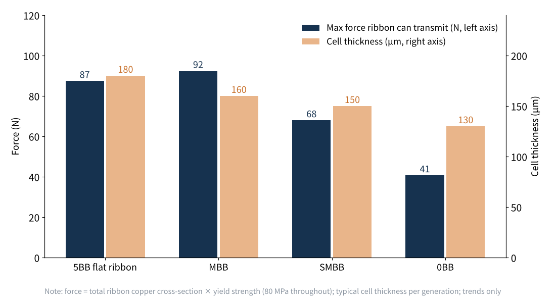
Figure 2 Maximum force ribbon can transmit vs. cell thickness across generations (estimate)
An interesting finding: from MBB to SMBB to 0BB, although the number of ribbons has grown, the drop in total copper cross-section from thinner individual ribbons effectively "lightens the load" on ever-thinner cells. This means finer ribbon is not just about saving silver and reducing shading; it is also one of the conditions that allow cells to get thinner. Conversely, if ribbon yield strength is not controlled in step, the cracking risk from thinner cells will be amplified.
Second, matching cell metallisation. At the other end of the joint is the cell's silver metallisation. Several issues need attention:
- Silver leaching: during soldering, molten solder dissolves silver from the metallisation; the finer the fingers and the thinner the silver layer, the greater the risk of it being "eaten". Adding a little silver to the coating (as in tin-lead-silver) suppresses this, and the ageing study mentioned in the previous article also showed slower degradation in joints with silver-containing solder.
- Low-temperature silver paste: HJT cells use low-temperature-cured silver paste, which bonds to solder differently from high-temperature fired paste, so both the ribbon coating and soldering process need dedicated matching.
- Direct contact with fingers: once 0BB removes the busbars, ribbon contacts the fingers directly over a small area, placing higher demands on the wetting of the ribbon coating and the consistency of its diameter.
Third, matching encapsulants. Ribbon is wrapped in encapsulant for twenty or thirty years, and their interaction cannot be ignored:
- Lamination process: lamination temperature and pressure act on the ribbon, and in 0BB routes joints are even formed directly during lamination, so the coating's melting point must match the lamination process.
- Chemical compatibility: EVA produces acetic acid under damp heat, and flux residue may react with the encapsulant; both directly affect joint corrosion and yellowing. The Kiwa PVEL 2026 report also observed that an improper flux recipe can cause delamination spreading from string busbars.
- Mechanical cushioning: the modulus and thickness of the encapsulant determine how much stress it can "cushion" for ribbon and cell; the finer the ribbon, the more important the encapsulant's protection of the cell gap. This needs particular verification when encapsulants are thinned to cut cost.
Ribbon reliability depends not only on the ribbon itself but on how well it matches cell thickness, cell metallisation and encapsulant.
05Improving module reliability through ribbon
Drawing together the previous articles, we suggest focusing on the following to improve module reliability from the ribbon side:
- Hold the yield strength window: yield strength is the ribbon parameter that most directly affects cracking. Set upper and lower limits according to cell thickness and soldering process, and keep monitoring batch variation in incoming inspection.
- Optimise the cell-gap design: the cell gap is the ribbon's most vulnerable spot. Flattened sections, segmented ribbon and stress-relief bends all reduce bending stress in the interconnect ribbon.
- Choose a suitable coating system: while meeting soldering process needs, pay attention to the coating's fatigue resistance and its ability to suppress silver leaching; for low-temperature ribbon, focus on verifying thermal cycling performance.
- Give the busbar area special attention: it carries the highest current, and soldering quality of its joints and lead-outs directly affects hot spots and safety, so it needs separate control.
- Retest after any material change: when ribbon specification, coating system or supplier changes, re-verify TC, DH, mechanical load and other relevant tests following retesting guidelines such as IEC TS 62915:2023, rather than assuming from experience that "it will be fine".
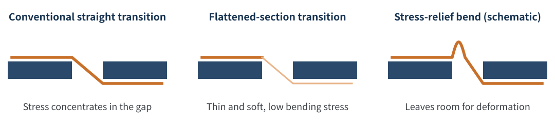
Figure 3 Several ways of routing ribbon across the cell gap (schematic)
One last point to stress: reliability verification must use the "real BOM". If any of ribbon, encapsulant, flux or cell differs from mass production, test results may be misleading. Even swapping a single flux or encapsulant can cause discolouration around the ribbon in a DH test that previously passed.
06Final thoughts
In short, reliability tests use acceleration to "rehearse" in advance the trials ribbon will face over decades outdoors, and ribbon selection and design are essentially preparation for that exam. Whether a ribbon is a good choice ultimately depends on how well it works with the whole module.
The next article, the last in this series, turns from technology to industry: the current state and direction of the ribbon industry, including the main Chinese suppliers, price structure, and technology trends such as 0BB, dedicated BC ribbon, lead-free coatings and cost-saving materials. Have you run into any ribbon-related "surprises" in reliability testing? We would be glad to hear from you.
References
- IEC 61215-2:2021 Terrestrial photovoltaic (PV) modules – Design qualification and type approval – Part 2: Test procedures (MQT 11 thermal cycling, MQT 13 damp heat, MQT 20 dynamic mechanical load, etc.).
- IEC TS 63209-1:2021 Photovoltaic modules – Extended-stress testing – Part 1: Modules.
- IEC TS 62915:2023 Photovoltaic (PV) modules – Type approval, design and safety qualification – Retesting.
- Gopalakrishna H. et al., Activation Energy for End-of-Life Solder Bond Degradation: Thermal Cycling of Field-Aged PV Modules, IEEE Journal of Photovoltaics (2020), https://www.osti.gov/pages/biblio/1770900
- IEA PVPS Task 13: Review of Failures of Photovoltaic Modules, https://iea-pvps.org/wp-content/uploads/2020/01/IEA-PVPS_T13-01_2014_Review_of_Failures_of_Photovoltaic_Modules_Final.pdf
- pv magazine USA: Latest RETC solar module quality report reveals significant issues, 2026-06-03, https://pv-magazine-usa.com/2026/06/03/latest-retc-solar-module-quality-report-reveals-significant-issues/
- Solar Power World: Latest PV module reliability scorecard shows unsettling uptick in failures, 2026-05-27, https://www.solarpowerworldonline.com/2026/05/latest-pv-module-reliability-scorecard-shows-unsettling-uptick-in-failures/
- Kiwa PVEL: 2026 Scorecard failures (EU PVSEC 2026), https://www.kiwa.com/globalassets/us/pvel/news/kiwa-pvel-2026-eupvsec-scorecard-failures.pdf.pdf
A PV R&D and technology team with 10+ years of experience | In-depth technical knowledge sharing
Materials · Reliability · Failure Analysis · Standards & Certification · Products · Processes
Exploring AI + PV; collaboration welcome
Disclaimer:
1. Original content reflects the authors' personal views only, is for reference only and does not constitute investment advice.
2. Reposted and cited content is credited to its source, out of respect for original work.
3. Some content was produced with AI assistance (chart generation, data retrieval, concept explanations, etc.); the core framework and key content were written by our technical team and reviewed by people.
4. If anything is inaccurate or infringes your rights, please leave a message or contact us and we will deal with it.