
Is the Ribbon Good? PV Ribbon Test Methods and Key Indicators
In brief
Whether a spool of ribbon goes onto the stringer should be decided by test data. Using the Chinese national standard GB/T 31985 and the industry association standard T/CPIA 0005 as references, this article sorts ribbon tests into five groups (dimensions and appearance, mechanical properties, electrical properties, coating and soldering, and environmental durability), explains how each is tested, what the standards require and where the pitfalls are, and closes with a tiered approach to incoming inspection at module plants.
In the previous article we walked down the production line and saw how ribbon's dimensions, temper and coating are "made". So at the module plant, how do you tell whether a spool of ribbon is good? Can the numbers on the datasheet be trusted? Which indicators must be tested on every batch, and which can be tested periodically? In this article we look at ribbon test methods and key indicators.
01The big picture: what to test
China has two main standards for ribbon: the national standard GB/T 31985—2015 Tin-coated copper ribbon for photovoltaics, and the China Photovoltaic Industry Association (CPIA) standard T/CPIA 0005—2017 of the same name. Their indicator frameworks are broadly the same and fall into five groups:
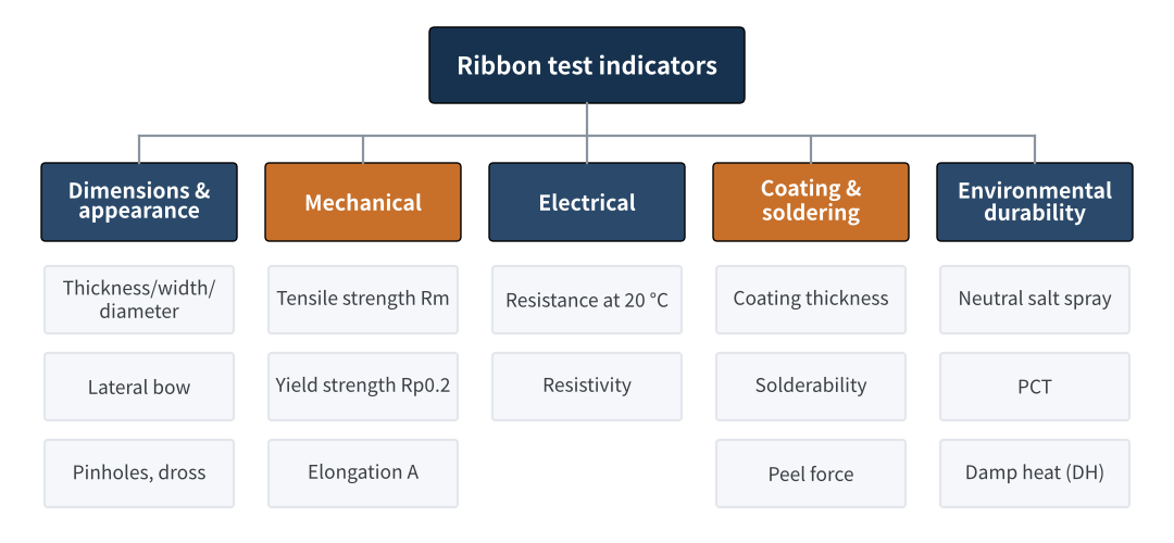
Figure 1 PV ribbon test indicator framework
These five groups map onto the three roles of ribbon we covered in the first article: dimensions and electrical properties govern "conduction", while mechanical properties and coating/soldering govern "connection"; dimensions and appearance also affect "optics". Environmental durability answers one question: can these properties hold up outdoors for twenty or thirty years?
We go through each group below. Values quoted are mainly from T/CPIA 0005—2017. Note that when this standard was written, the industry still mostly used flat ribbon; today 0.18 mm and 0.20 mm round-wire ribbons for 0BB are in mass production, so some requirements for round-wire, shaped and low-temperature ribbons need to be added by module makers and suppliers in their technical agreements.
02Dimensions and appearance: the most basic, and the most overlooked
Dimensions are the most basic indicator, but not a simple one. T/CPIA 0005 requires the following for flat ribbon:
- Thickness tolerance: ±0.01 mm.
- Width tolerance: ±0.08 mm.
- Lateral bow: no more than 5 mm/m, the so-called "sickle bend". Ribbon with large bow tends to wander during stringing, causing misaligned soldering and exposed busbar.
- Appearance: no more than 3 pinholes or dross spots per 10 cm, each smaller than 0.5 mm²; no oxidation discolouration, bare spots or similar defects.
For round-wire ribbon, the focus is diameter, roundness and straightness. As we calculated in the previous article, the same 0.01 mm undersize raises a 0.18 mm ribbon's resistance by more than 12%. So diameter measurement of ultra-fine ribbon cannot rely on spot checks with a micrometer; continuous methods such as laser gauging are increasingly necessary.
Another easily overlooked detail: is the measured value the "diameter including coating" or the "copper core diameter"? The two can differ by tens of micrometres. This must be stated clearly in datasheets and agreements, or the supplier's and the buyer's data will never match.
03Mechanical properties: yield strength is what matters
Mechanical properties are measured by tensile testing according to GB/T 228.1 Metallic materials — Tensile testing — Part 1: Method of test at room temperature (current edition 2021), with a 100 mm gauge length. One tensile test gives three indicators:
- Tensile strength Rm: the maximum stress before fracture, showing how "strong" the ribbon is.
- Yield strength Rp0.2: the stress at 0.2% permanent deformation, showing how "soft" the ribbon is.
- Elongation after fracture A: the percentage elongation at fracture, showing the ribbon's "ductility".
| Indicator (T/CPIA 0005) | Interconnect · soft | Interconnect · extra-soft | Busbar ribbon |
|---|---|---|---|
| Tensile strength Rm (thickness >0.15 mm) | ≥150 MPa | ≥130 MPa | ≥170 MPa |
| Tensile strength Rm (thickness ≤0.15 mm) | ≥110 MPa | ≥100 MPa | ≥120 MPa |
| Elongation A (thickness >0.15 mm) | ≥25% | ≥20% | ≥25% |
| Elongation A (thickness ≤0.15 mm) | ≥15% | ≥15% | ≥18% |
| Yield strength Rp0.2 | By agreement | By agreement | Not specified |
Table 1 T/CPIA 0005 mechanical property requirements for ribbon
Note the last row: the standard gives no common value for yield strength, the property that most affects micro-cracking, and leaves it to agreement between supplier and buyer. The reason is that different cell thicknesses and soldering processes call for very different yield strengths, so one number cannot fit all.
This means module makers must set upper and lower limits for yield strength in their technical agreements. As we explained in the materials article, too high a yield strength damages cells and too low hurts production; it is a "window". 0BB narrows this window further: according to TaiyangNews, YourBuddy (Yubang New Materials) recommended a yield strength of about 106 MPa together with a tensile ratio of about 2% for its 0.20 mm low-temperature ribbon to reduce ribbon offset during soldering. Where the window sits depends on the combination of cell, soldering process and ribbon, and can only be set item by item in the agreement.
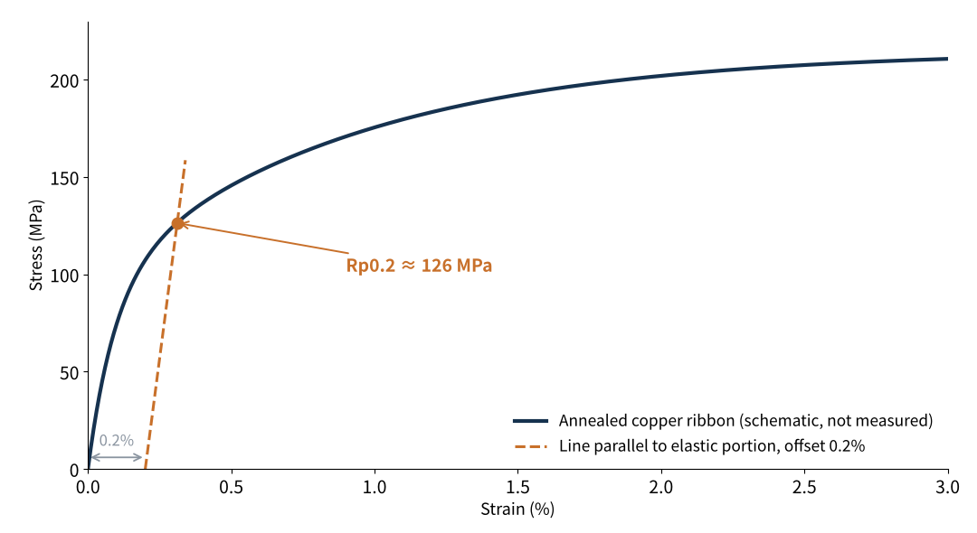
Figure 2 Determining Rp0.2: the 0.2% offset method (schematic)
Annealed copper has no distinct yield point, so the 0.2% offset method is used: draw a line parallel to the elastic portion starting at 0.2% strain; the stress where it meets the curve is Rp0.2. For very fine round wire the elastic portion is very short, so extensometer accuracy, gripping and whether the specimen has been straightened all noticeably affect the result. When the same spool gives different yield strengths in different labs, the cause is often not the ribbon but misaligned test methods.
Tensile strength and elongation have minimums in the standard; yield strength has to be set by agreement. Before measuring yield strength, align specimen preparation and extensometer settings with the supplier.
04Electrical properties: don't forget temperature correction
Ribbon resistance is measured by the method in GB/T 3048.2, usually with the four-terminal method: two terminals carry current and the other two measure voltage, avoiding errors from contact resistance. T/CPIA 0005 requires the ribbon's resistance at 20 °C to be lower than that of a copper substrate of the same size. For reference, the resistivity of annealed standard copper (100% IACS) is 0.017241 Ω·mm²/m.
The most common mistake in resistance measurement is forgetting temperature correction. Copper's temperature coefficient of resistance is about 3.93×10⁻³/°C, so resistance rises by about 0.4% for every 1 °C. If the lab is at 28 °C, the uncorrected resistance will read about 3.1% higher than at 20 °C, an error of the same order as the diameter deviation effect calculated in the previous article.
So the measured resistance should be converted to 20 °C: R₂₀ = Rₜ / [1 + 0.00393 × (t − 20)]. The standard also requires five measurements at 20 ± 5 °C, averaged, precisely to reduce this kind of error.
05Coating and soldering: thickness, solderability and peel force
There are two main ways to measure coating thickness. One is the metallographic microscope method (GB/T 6462): the ribbon cross-section is cut, mounted and polished, then measured directly under a microscope. The other is X-ray fluorescence (GB/T 16921), which is non-destructive and fast, suiting production sampling. In case of dispute, the metallographic method prevails. T/CPIA 0005 allows a tolerance of ±5 μm on single-side coating thickness, with the target thickness set by agreement.
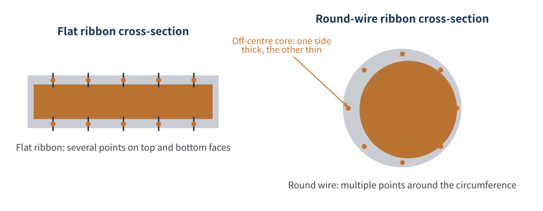
Figure 3 Measurement points for coating thickness (schematic)
For round wire, measuring one or two points is not enough. If the copper core is off-centre within the coating, the average thickness may pass while one side is very thin and the other very thick, making the amount of solder at the contact face unstable during soldering. Metallographic sections should be measured at several points around the circumference, recording both the maximum and the minimum.
Solderability is assessed by peel force: the ribbon is soldered to a standard test plate and then peeled at 180°, measuring the force during peeling. T/CPIA 0005 requires:
- Test conditions: peel speed 20 mm/min; effective soldered length at least 20 mm, with a plateau of at least 15 mm; soldering temperature 340 ± 5 °C for lead-containing solder and 370 ± 5 °C for lead-free solder.
- Acceptance: average peel strength at least 4.0 N/mm for tin-lead solder and at least 3.0 N/mm for lead-free solder.
There is a new issue here: these soldering temperatures were set for conventional tin-lead and lead-free solders. For low-temperature ribbons used in HJT and 0BB, such as tin-bismuth (eutectic about 138 °C) and SnPbBi (melting range about 93–150 °C), soldering temperature, test plates and acceptance values must be agreed separately; the 340 °C and 370 °C conditions cannot simply be applied.
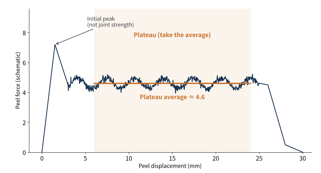
Figure 4 Typical peel force curve and plateau reading (schematic)
When reading a peel force curve, use the average over the plateau, not the initial peak. The initial peak comes mainly from stress concentration at the end of the joint and does not represent overall joint strength. Watch the fluctuation as well: an average that passes but with large swings often indicates uneven coating thickness or local cold joints.
Two things need to be kept apart here. What we described above is the "solderability" of the ribbon itself, which assesses the ribbon coating. The "cell soldering peel force" that module plants test routinely assesses the combination of ribbon, cell fingers/pads and soldering process; it can follow T/CSTM 00461—2022 Test method for peel strength of electrodes of crystalline silicon PV cells, which specifies a peel speed of 300–800 mm/min and different acceptance values. The two tests have different purposes and conditions, and their data cannot be compared directly. Also, N/mm is a unit normalised by ribbon width, and for round wire there is no common way to define "width"; many companies simply use N, which also needs to be stated in the agreement.
For coating, look at uniformity as well as thickness; for peel force, look at the plateau average and also at the fluctuation. Ribbon solderability and cell soldering peel force are two different tests; don't mix their data.
06Environmental durability: can it last twenty or thirty years?
The indicators so far describe the "as-shipped" state. Environmental durability tests answer whether the ribbon stays stable under humidity, heat and salt mist. T/CPIA 0005 specifies three:
| Test | Conditions | Acceptance |
|---|---|---|
| Neutral salt spray | GB/T 10125, 48 h | Protection rating 10, appearance rating at least 4; no yellowing, blackening, peeling or blistering |
| PCT (pressure cooker test) | 121 °C, 99–100% RH, 24 h | No obvious yellowing or blackening within 10 mm on either side of the ribbon |
| Ageing resistance (damp heat) | 85 °C, 85% RH, 1,000 h | No obvious yellowing or blackening within 10 mm on either side of the ribbon |
Table 2 Environmental durability tests for ribbon in T/CPIA 0005
The acceptance criteria for the last two are telling: they look not at the ribbon itself but at whether there is yellowing or blackening within 10 mm on either side of it. This shows they are really testing compatibility between ribbon and encapsulant: under damp heat, the ribbon coating, flux residue and encapsulant film can interact, causing the film to yellow and the ribbon to corrode and blacken.
These tests take a long time and are not suited to every batch, but they must be done when introducing a new supplier, a new coating system or a new encapsulant, ideally together with the encapsulant and flux actually used. For bismuth-containing low-temperature coatings, corrosion resistance and shelf life should be verified separately.
07Incoming inspection: making it effective
With the indicators and methods clear, we suggest organising incoming inspection at module plants in tiers:
| Tier | Frequency | Suggested tests |
|---|---|---|
| Every batch | Each incoming batch | Appearance, dimensions (diameter/thickness and width), tensile (Rm, Rp0.2, A), coating thickness |
| Periodic | Monthly or by batch ratio | Resistance, solderability peel force, lateral bow, roundness |
| Qualification and change | New supplier, new specification, process change | Salt spray, PCT, damp heat; compatibility with encapsulant and flux |
Table 3 Suggested tiers for incoming ribbon inspection
On top of this, a few practices work well:
- Sample both the start and the end of the spool: annealing and coating variation often occurs at start-up and spool changes, so sampling only the start of the spool can miss problems.
- Look at distributions, not single points: one passing sample does not mean the whole batch is stable. Recording data for every batch and watching for mean drift and spread is worth more than "pass/fail".
- Watch storage: once a pack is opened, the coating gradually oxidises and solderability falls. Passing incoming inspection does not mean the ribbon still passes when it goes on the line, so control opened time and storage conditions.
- Fill the gaps in the agreement: the standard is a floor. The yield strength window, round-wire diameter and roundness, target coating thickness, test conditions for low-temperature ribbon, and the units and conditions for peel force should all be written into the technical agreement.
The standard only sets the floor. What really determines stringing yield and long-term reliability are the few key indicators written clearly into the agreement, and consistently stable batch data.
08Final thoughts
The difficulty in ribbon testing is often not the instruments but "alignment": what to test, how to sample, how to correct and how to judge. Supplier and buyer need to speak the same language first. When the data don't match, check the method first and the ribbon second; this is a lesson we have confirmed repeatedly in managing incoming material.
Once the ribbon passes, the next step is soldering it to the cell. In the next article we look at soldering processes: stringing methods such as infrared and electromagnetic induction soldering, low-temperature soldering, and 0BB busbar-free interconnection. Have you run into test data that just wouldn't match between labs? We would be glad to hear from you.
References
- GB/T 31985—2015 Tin-coated copper ribbon for photovoltaics (standard listing), https://www.chinesestandard.net/PDF/English.aspx/GBT31985-2015
- T/CPIA 0005—2017 Tin-coated copper ribbon for photovoltaics, China Photovoltaic Industry Association, https://www.ttbz.org.cn/Home/PdfFileStreamGet/c3QsMjIyMjc(eq)
- T/CSTM 00461—2022 Test method for peel strength of electrodes of crystalline silicon PV cells, https://www.ttbz.org.cn/Home/PdfFileStreamGet/c3QsNjI0Mjk(eq)
- GB/T 228.1—2021 Metallic materials — Tensile testing — Part 1: Method of test at room temperature; GB/T 3048.2 Test methods for electrical properties of electric cables and wires — Part 2: Electrical resistivity of metallic materials; GB/T 6462 Metallic and oxide coatings — Measurement of coating thickness — Microscopical method; GB/T 16921 Metallic coatings — Measurement of coating thickness — X-ray spectrometric methods; GB/T 10125—2021 Corrosion tests in artificial atmospheres — Salt spray tests.
- TaiyangNews: YourBuddy: Ribbons For 0BB Metallization, 2025-01-28, https://taiyangnews.info/technology/yourbuddy-ultra-thin-low-temperature-0bb-metallization
A PV R&D and technology team with 10+ years of experience | In-depth technical knowledge sharing
Materials · Reliability · Failure Analysis · Standards & Certification · Products · Processes
Exploring AI + PV; collaboration welcome
Disclaimer:
1. Original content reflects the authors' personal views only, is for reference only and does not constitute investment advice.
2. Reposted and cited content is credited to its source, out of respect for original work.
3. Some content was produced with AI assistance (chart generation, data retrieval, concept explanations, etc.); the core framework and key content were written by our technical team and reviewed by people.
4. If anything is inaccurate or infringes your rights, please leave a message or contact us and we will deal with it.