
Bonding Ribbon to Cell: A Complete Guide to PV Module Soldering
In brief
Ribbon is ultimately joined to the cell by soldering. Starting from how a single solder joint forms, this article walks through the stringer process, compares infrared, induction and other heating methods, uses thermal mismatch estimates to show the conflict between a strong joint and an undamaged cell, introduces low-temperature soldering for HJT and the main 0BB (zero-busbar) interconnection routes, and ends with a troubleshooting guide for common soldering problems.
In the previous five articles we covered ribbon itself thoroughly: its roles, forms, materials, manufacturing and testing. But ribbon's value is ultimately realised in one place: the solder joint. A module has tens of thousands of joints, and any cold joint, over-soldered joint or micro-crack leaves a mark on the EL image and may, years later, turn into power loss or a hot spot. In this article we look at how ribbon and cell are "bonded".
01How a solder joint forms
Soldering ribbon to a cell is essentially soft soldering: heat melts the tin alloy coating on the ribbon, the molten solder wets the cell's silver fingers or pads, a metallurgical reaction takes place at the interface, and on cooling it solidifies into a strong connection.
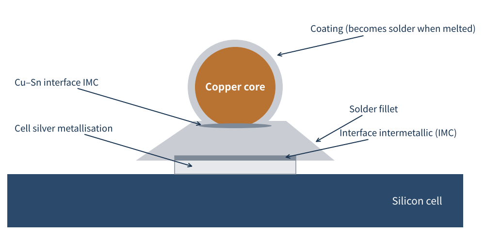
Figure 1 Structure of a solder joint between ribbon and cell metallisation (schematic)
The process has three stages:
- Wetting: flux first removes the oxide films from the ribbon coating and the silver metallisation so the molten solder can spread over it. With poor wetting the solder merely "sits" on the metallisation; it looks soldered but is actually a cold joint.
- Alloying: tin in the solder reacts with silver in the metallisation and copper in the ribbon, forming a very thin layer of intermetallic compound (IMC) at the interface. It is this IMC that makes the joint truly "grow" together.
- Solidification: once heating stops, the solder cools and solidifies and the joint takes shape. During cooling, the different shrinkage of copper and silicon starts to generate stress.
Joint quality is determined by four factors: temperature, time, pressure and flux. Temperature and time decide whether the solder melts fully and the IMC grows properly; pressure keeps the ribbon in close contact with the metallisation; flux ensures wetting. A problem with any one of the four means a problem with the joint.
02What happens inside the stringer
At the module plant, soldering is done on a stringer, which solders cells and ribbons together one by one into a cell string. A typical flow:
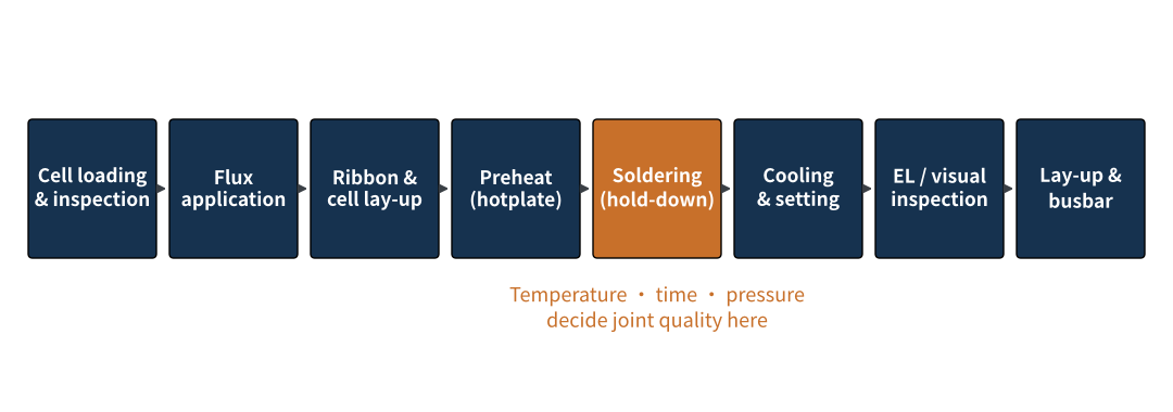
Figure 2 Typical stringer process flow (schematic)
- Loading and inspection: after loading, cells undergo visual or EL inspection to reject those already cracked or chipped, so problems are not carried into the string.
- Flux application: flux is applied at the soldering positions on the ribbon or cell. Too little gives poor wetting; too much increases residue, affecting appearance and long-term reliability.
- Ribbon and cell lay-up: ribbon is cut to the design length, straightened and precisely aligned with the cell. With a dozen to over twenty fine round wires, alignment accuracy directly decides whether joints end up misaligned.
- Preheating: cells sit on a heated plate to reduce the instantaneous temperature difference during soldering and lower thermal shock.
- Soldering: the ribbon is pressed down by hold-down tools (pins or plates) while being heated rapidly so the coating melts and the joint forms. This is the core of the whole flow.
- Cooling and inspection: once the joints have cooled and set, the string goes through EL and visual inspection before moving on to lay-up and busbar soldering.
The whole soldering cycle usually takes only a second or two. Getting more than a thousand joints to the right temperature at the same time in that short window places high demands on the uniformity and controllability of the heating method.
03Heating methods: infrared, induction or laser
Stringers mainly use the following heating methods, each with its own characteristics:
| Heating method | Principle | Advantages | Points to watch |
|---|---|---|---|
| Infrared | Radiant heating by IR lamps | Non-contact, fast, mature | Uniformity depends on lamp layout and shading |
| Electromagnetic induction | Induction coil makes the ribbon heat itself | Heat concentrated in the ribbon, less heat into the cell | Sensitive to ribbon material and position; demanding to set up |
| Hot air | Convective heating by hot air | Uniform temperature, low thermal shock | Relatively slow |
| Laser | Laser heats joints locally | Precise heating area, small heat-affected zone | High equipment cost; hard to heat many joints at once |
Table 1 Main stringer heating methods compared
Infrared heating is currently the most widely used. A Fraunhofer ISE team in Germany published a modelling study of infrared soldering in an industrial stringer in EPJ Photovoltaics in 2025, validated against thermocouple measurements of cell temperature during soldering, with a maximum difference between simulation and measurement of (8 ± 4) K. Its data are a useful reference:
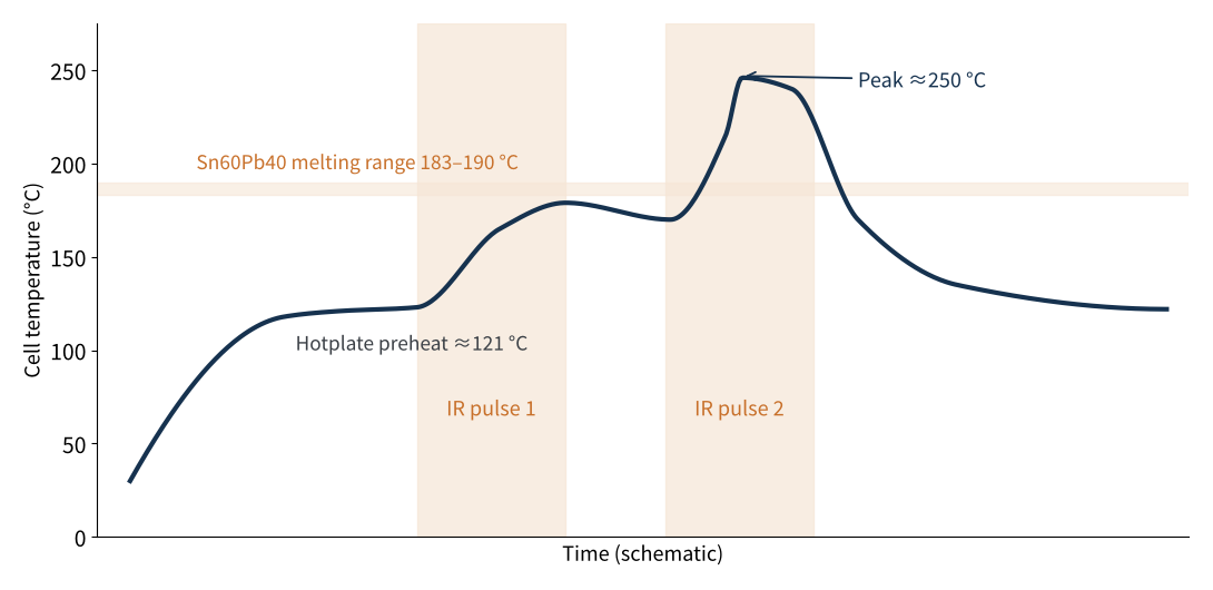
Figure 3 Cell temperature during infrared soldering (schematic, redrawn from a Fraunhofer ISE case study)
- Two-pulse heating: the hotplate preheats the cell to about 121 °C; two IR pulses of about 1.2 s then raise the cell first to about 180 °C and then to a peak of about 250 °C.
- Hot centre, cool edges: the cell edges are about 26–36 °C cooler than the centre, because IR intensity falls off from the centre to the edges, with shading and reflection by the hold-down tools also playing a part.
- Higher power, less uniformity: cutting IR power from 70% to 50% narrowed the centre-to-edge difference from about 36 °C to about 26 °C, and lowered the peak temperature from about 249 °C to about 219 °C.
These data reveal a practical problem: to get the edge joints fully soldered, the centre is often "over-heated". Uneven temperature means the same cell may carry both over-soldering and cold-joint risks, as well as higher thermal stress. This is why stringer process tuning pays particular attention to differences in peel force between joints at the cell edge and in the centre.
This can be optimised. At the 2025 European PV Solar Energy Conference (EU PVSEC), the same team reported measured temperature inhomogeneity of more than 40 K for heterojunction cells in industrial IR soldering; by optimising the power split between IR lamps and shortening the pulse from 1.2–1.3 s to 1 s, their simulation brought it down to about 17 K for an M6 half-cell and about 15 K for an M10 half-cell. How lamp power is distributed is as much a tuning parameter as the ribbon and solder themselves.
The heating method decides where the heat goes. Infrared is the most mature but uniformity is an inherent challenge, which power distribution and pulse design can ease; induction and laser are better at "heating only the joint and less of the cell".
04The temperature window: strong joints vs. undamaged cells
Why can't soldering temperature simply be turned up? Because it directly sets the thermal stress after cooling. As we explained in the materials article, copper's coefficient of linear expansion is about 17×10⁻⁶/K and silicon's only about 2.6×10⁻⁶/K. When the solder solidifies, ribbon and cell are "locked" together; as they cool to room temperature, copper shrinks more than silicon. This is the thermal mismatch strain.
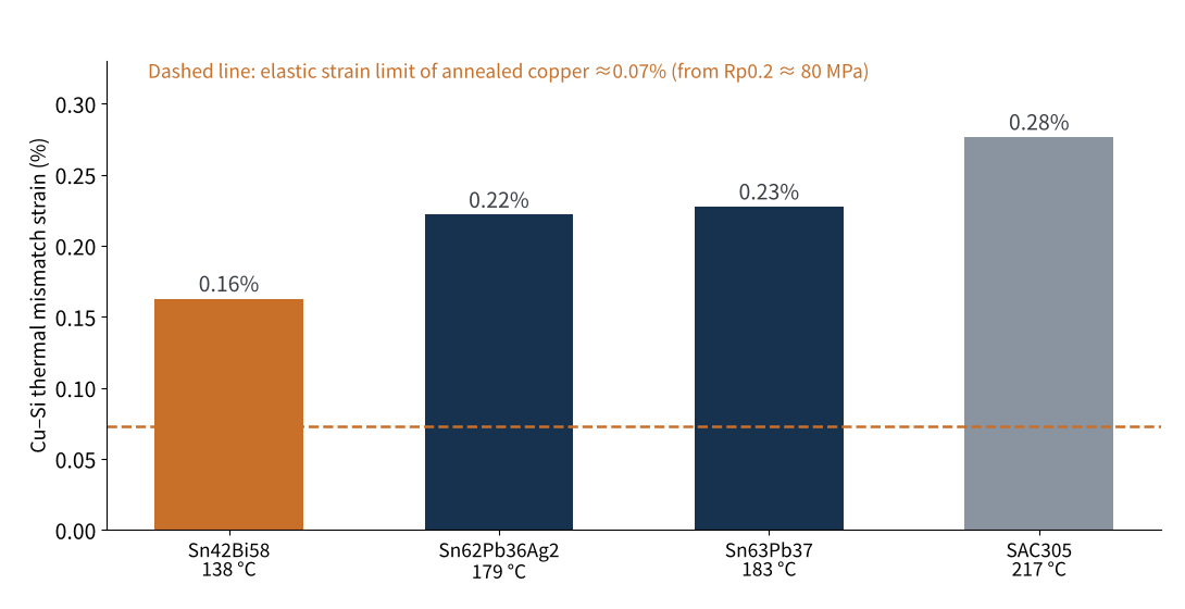
Figure 4 Estimated copper–silicon thermal mismatch strain for different solder solidification temperatures
Taking common tin-lead solder (solidifying at 183 °C) as an example, the thermal mismatch strain of copper relative to silicon on cooling to 25 °C is about 0.23%. The elastic strain limit of annealed copper is only about 0.07%. In other words, the thermal mismatch strain is about three times copper's elastic range, so copper ribbon inevitably yields plastically during cooling.
This conclusion is key. Since the ribbon is bound to yield, the stress finally "pulling" on the cell is set mainly by the ribbon's yield strength, not linearly by the soldering temperature. That is why the materials and testing articles keep stressing yield strength: soft ribbon uses its own plastic deformation to "absorb" stress on behalf of the cell.
Soldering temperature matters in two ways. First, the lower the solidification temperature, the smaller the thermal mismatch strain; tin-bismuth solder (138 °C), for example, reduces it by about 30% compared with tin-lead. Second, the higher the peak temperature and the less uniform the heating, the larger the transient temperature differences and warpage inside the cell. So lowering soldering temperature and improving temperature uniformity are both effective ways to reduce micro-cracks.
But temperature cannot be lowered indefinitely. Too little heat causes cold joints: the solder does not wet fully, the IMC does not form properly, peel force is low, and the joint is more likely to crack in later thermal cycling. The soldering "temperature window" is the safe band between cold joints and micro-cracks, and the thinner the cell and the finer the ribbon, the narrower that window becomes.
Copper ribbon always yields on cooling, so controlling yield strength is the fundamental way to reduce stress; lowering soldering temperature and improving heating uniformity are the two process levers.
05Low-temperature soldering: making way for heat-sensitive cells
For heterojunction (HJT) cells, soldering temperature is a hard constraint. The amorphous silicon passivation layers and transparent conductive films on HJT cells are temperature-sensitive, and process temperatures are generally held below about 200 °C, or passivation and film performance degrade. Peak temperatures in conventional tin-lead soldering clearly exceed this range, so HJT needs dedicated low-temperature interconnection:
- Low-temperature ribbon: coatings with low melting points, such as tin-bismuth, allow much lower soldering temperatures. The challenge is that bismuth is brittle, so joint fatigue resistance must be fully verified by thermal cycling.
- Electrically conductive adhesive (ECA): an adhesive containing conductive particles such as silver replaces solder and cures at room or low temperature. It brings low temperature and low stress, but material cost is higher, and conductivity and long-term bond reliability need verification.
- Busbar-free interconnection: busbars are removed and ribbon is connected with the help of encapsulant film or adhesive, with joints forming during lamination. This is 0BB, covered in the next section.
Notably, demand for low-temperature soldering no longer comes only from HJT. As cells keep getting thinner, TOPCon and BC cells face the same warpage and cracking pressure. According to TaiyangNews in February 2026, conventional stringing solders at about 240 °C, and because all contacts on a BC cell are on the rear side, the heat can make the cells bow, leading to cracks and breakage. The tape-based interconnection from Sweden's Sticky Solar Power targets this problem: copper wires are first attached to 5–7 mm wide tape strips, stringing is done without heating, and the electrical connection forms during lamination at a maximum of about 160 °C, with a single-lane throughput of about 5,000 cells per hour.
060BB: moving soldering into the laminator
0BB (zero busbar) is the biggest change in soldering processes in recent years. Busbars are no longer printed on the cell, and ribbon is pressed directly onto the fingers. Its defining feature is that the electrical connection between ribbon and fingers is often made not in the stringer but during lamination. The stringer only "fixes" the ribbon in the right position. According to TaiyangNews' Cell & Module Technology Trends 2026 report, nearly every leading supplier introduced a 0BB module in 2025 and showed it at major trade shows, with silver reduction as the main driver.
Depending on how the ribbon is fixed and connected, there are currently three main routes:
| Route | Method | Advantages | Challenges |
|---|---|---|---|
| Soldering + dispensing | Ribbon is soldered to the cell, then fixed with adhesive or tape | Strong bond, reworkable, uses existing equipment | Demanding soldering, high dispensing accuracy, slower |
| Dispensing + alloying in lamination | UV or hot-melt adhesive is dotted on the cell, ribbon pressed on, alloyed connection forms in lamination | Replaces the soldering step, wider stringing process window | Needs protective film; defects only found after lamination |
| Film covering (integrated film) | Encapsulant film, cells and ribbon laminated into a string in one step, no flux | High ribbon-to-cell adhesion, ribbon unlikely to detach from fingers | Needs dedicated film and rework equipment; defects only found after lamination |
Table 2 Main 0BB interconnection routes compared
0BB also places new requirements on ribbon itself:
- Coating melting point must match lamination: the connection forms during lamination, so the ribbon coating must melt and wet fully at lamination temperature; low-melting coatings are favoured.
- Finer, more consistent diameter: with no busbar as a "safety net", ribbon is pressed directly onto very fine fingers, so deviations in diameter and straightness turn directly into poor contact.
- Compatibility with encapsulant and adhesive: the ribbon coating, encapsulant film and adhesive act together in lamination, so all three must be verified together; changing any one material can affect connection quality.
Another change 0BB brings is that quality inspection moves downstream. With conventional stringing, soldering problems can be found by EL right after stringing, but some 0BB defects only appear after lamination, and once found they affect the whole module. The stability and process control of upstream steps matter more than ever.
The direction of soldering process development is clear: lower temperatures, more concentrated heat and a later connection point, all aimed at making strong joints on ever-thinner cells without damaging them.
07Quick troubleshooting guide
Finally, we have summarised the most common stringing problems and where to look into one table for production lines:
| Symptom | Common causes | Where to look |
|---|---|---|
| Cold joints, low peel force | Insufficient temperature, too little or degraded flux, oxidised or thin coating | Check heating power and time, flux, ribbon storage and coating thickness |
| Over-soldering, yellowed joints | Temperature too high, time too long | Reduce power or shorten time; check temperature uniformity |
| Micro-cracks, breakage | High yield strength, uneven temperature, excessive hold-down pressure | Check ribbon yield strength, improve preheating and heating uniformity, inspect hold-down tools |
| Misaligned joints, exposed fingers | Large ribbon bow, alignment error | Check ribbon straightness and lateral bow; recalibrate alignment |
| Solder balls, solder overflow | Coating too thick, temperature too high | Check coating thickness; adjust temperature |
| String warpage | High thermal mismatch stress, ribbon too hard | Lower soldering temperature, choose softer ribbon, optimise cooling |
Table 3 Common stringing problems and where to look
As the table shows, many soldering problems are rooted not in the stringer but in the ribbon itself: yield strength, coating thickness, straightness and storage condition. That is why the earlier articles spent so much space on ribbon materials, manufacturing and testing. Soldering is the "final exam" for every property of the ribbon.
08Final thoughts
A good solder joint is the combined result of ribbon, cell, flux, equipment and process parameters. From conventional stringing to 0BB, the form of soldering keeps changing, but the core conflict has not: the joint must be strong without damaging the cell. Understand this, and the logic behind each step in the evolution of soldering processes becomes clear.
Once the joints are made, can they last twenty or thirty years outdoors? In the next article we look at common ribbon-related failures: cold joints, micro-cracks, joint fatigue, corrosion and hot spots, and how EL and cross-section analysis trace failures to their root causes. What is the most troublesome soldering problem on your line? We would be glad to hear from you.
References
- Joseph et al., Simulation of infrared soldering of solar cells in an industrial stringer, EPJ Photovoltaics 16, 9 (2025), https://www.epj-pv.org/articles/epjpv/full_html/2025/01/pv20240061/pv20240061.html
- Joseph et al., Fraunhofer ISE, 41st EU PVSEC 2024 conference paper (IR soldering model, 60% power baseline), https://www.ise.fraunhofer.de/content/dam/ise/de/documents/publications/conference-paper/41th-eu-pvsec-2024/Joseph_Paper.pdf
- Joseph et al., Fraunhofer ISE, 42nd EU PVSEC 2025 poster (optimising IR soldering temperature uniformity), https://www.ise.fraunhofer.de/content/dam/ise/de/documents/publications/conference-paper/42nd-eupvsec-2025/Joseph_3AV17_Poster.pdf
- SMM: 0BB Technology and Cost of Encapsulation Film for Different Routes Part 1, https://news.metal.com/newscontent/103121370/[SMM-Analysis]-0BB-Technology-and-Cost-of-Encapsulation-Film-for-Different-Routes-Part-1
- TaiyangNews: Sticky Solar Highlights Tape-Based Stringing For Advanced PV Cells, https://taiyangnews.info/technology/sticky-solar-highlights-tape-based-stringing-for-advanced-pv-cells
- TaiyangNews: Tape-Based Interconnection Approach For BC Modules, 2026-02-25, https://taiyangnews.info/technology/tape-based-interconnection-approach-for-bc-modules
- TaiyangNews: Gapless, Full-Screen, And 0BB Redefine Module Assembly, 2026-07-03, https://taiyangnews.info/technology/gapless-full-screen-and-0bb-redefine-module-assembly
- Coefficients of linear expansion of copper and silicon and melting points of solder alloys are general reference values.
A PV R&D and technology team with 10+ years of experience | In-depth technical knowledge sharing
Materials · Reliability · Failure Analysis · Standards & Certification · Products · Processes
Exploring AI + PV; collaboration welcome
Disclaimer:
1. Original content reflects the authors' personal views only, is for reference only and does not constitute investment advice.
2. Reposted and cited content is credited to its source, out of respect for original work.
3. Some content was produced with AI assistance (chart generation, data retrieval, concept explanations, etc.); the core framework and key content were written by our technical team and reviewed by people.
4. If anything is inaccurate or infringes your rights, please leave a message or contact us and we will deal with it.