
It Plugs In, But Does It Mate? How Micron-Scale Slip in Cross-Mated PV Connectors Grinds Its Way to a Fire
A module ships with brand-A connectors, the extension cable carries brand B, both are labelled “MC4-compatible” and click together perfectly — yet a few years later the joint can be a charred lump. Starting from differences in contact-spring design, plating and tolerances, this article unpacks the micron-scale fretting driven by day–night temperature swings, works through the heat budget from milliohms to fire, clarifies what IEC 62852, IEC 62548 and related standards actually require, and closes with a practical checklist for EPC and O&M teams.
In thermal-imaging surveys of PV plants, the most common “little fire” is often not in a module at all, but at the joint between two cables. Open it up and you find a brand-A plug on the module side and a brand-B socket on the extension cable, both housings printed “MC4-compatible”, and the mating felt perfectly smooth. That is exactly the problem — plugging in is not the same as mating. Here we take this “banned but still everywhere” practice apart from the angle of materials and contact physics.
01 The most common scene on site
In a string, connectors sit in three kinds of position: module to module (factory-fitted, same brand, fewest problems); module to extension cable; and extension cable to combiner box or inverter. The last two are where cross-mating concentrates — the module maker picks connectors from its own BOM, the inverter ships with mating plugs of another brand, and the field-crimped connectors in the installer’s toolbox may be a third brand.
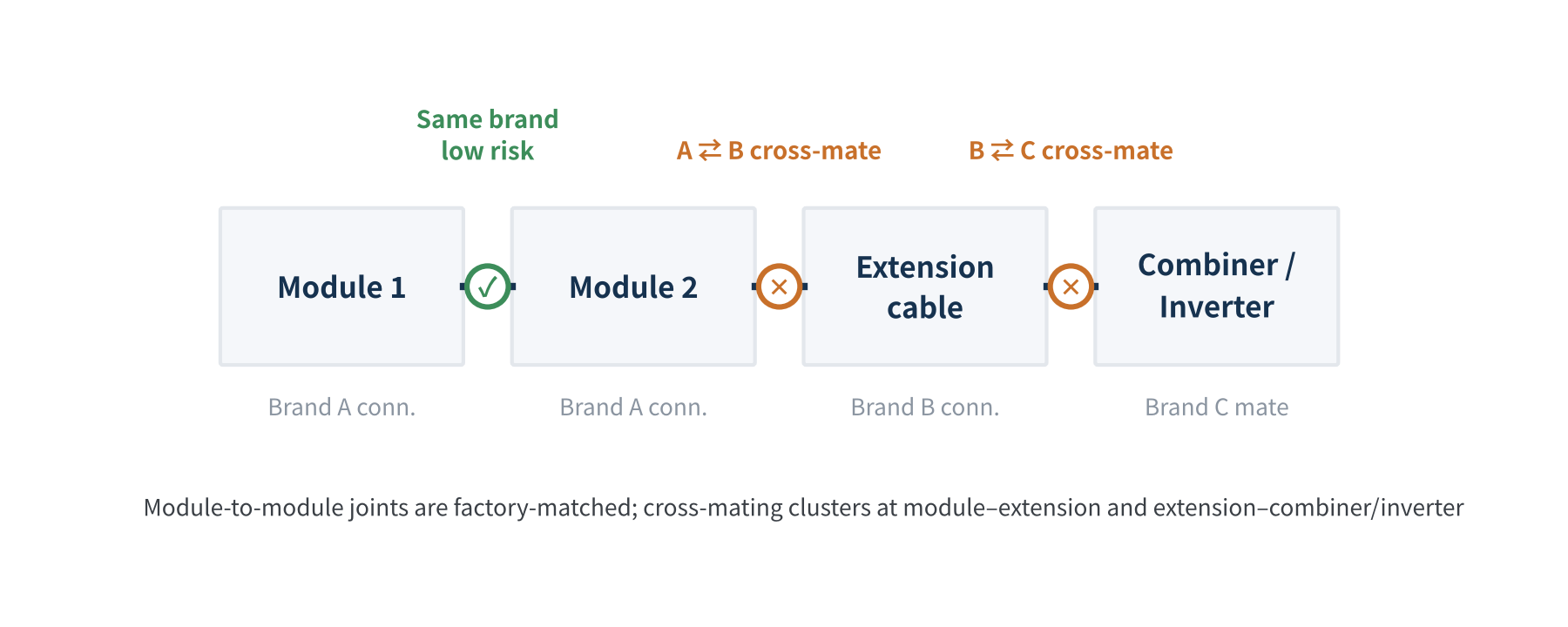
Figure 1 Where cross-mating typically occurs in a string
This is not an isolated issue. In 2019 the Netherlands Organisation for Applied Scientific Research (TNO) investigated a series of rooftop PV fires and found about 70% were connector-related, with cross-mating the main cause. CEA inspections of rooftop systems found cross-mated connectors at about 41% of sites. HelioVolta’s 2025 review of inspections covering more than 5 GW found that 83% of projects had at least one connector issue, and that avoidable causes — cross-mating, exposure to the elements, and incorrect torque — made up over 60% of all connector issues.
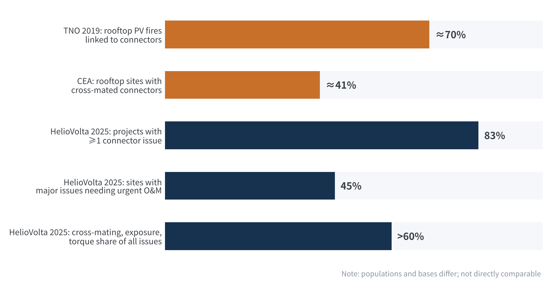
Figure 2 Connector-issue shares in several third-party surveys (bases differ)
02 “MC4-compatible” only means the outside fits
“MC4” is a registered trademark of Stäubli that has become the generic name for this class of 4 mm round-pin connector. What a “compatible” part guarantees is that the housing latches and pin diameter line up. What decides long-term reliability is the invisible contact interface, and there are at least three differences there:
- Contact-spring design: Some use multi-point louvre bands (e.g. MULTILAM), some slotted tulip springs, some stamped spring fingers. The number of contact points, the normal force per point and the elastic travel are entirely different. When brand A’s pin goes into brand B’s spring, nobody has jointly verified whose design window the normal force falls into.
- Plating system: Tin or silver, with or without a nickel underlayer, thickness anywhere from about 1 μm to several μm. With dissimilar platings, frictional transfer makes the interface behave increasingly like the softer, more easily oxidised side, and galvanic corrosion becomes a risk.
- Materials and tolerances: Phosphor bronze, beryllium copper or Cu-Ni-Si springs differ in elastic modulus and high-temperature stress relaxation; different PC/PA housing grades have different thermal expansion; pin-diameter tolerances are set against each maker’s own counterpart, and stacked together may land at the low-force end.
| Aspect | Same brand & type | Cross-mated brands |
|---|---|---|
| Contact geometry | Designed as a pair | Never co-designed |
| Contact normal force | Within design window | Possibly low, widely scattered |
| Plating | One system | Possibly dissimilar metals |
| Certification | Covered by type testing | Outside certificate scope |
Summary: What is compatible is “it plugs in”; what has never been verified is “it still connects well after 25 years”.
03 Fretting: how micron-scale slip drives up contact resistance
A connector looks static, but it moves every day. Module backsheet temperatures can exceed 70 °C by day and fall to ambient or below zero at night, and switching current adds Joule-heating pulses. Pin, spring and the two plastic housings all expand differently, so every temperature change produces micron-scale reciprocating slip between the contact points. This is fretting.
A rough estimate: with a difference of about 15×10⁻⁶/K in linear expansion between the two housing materials, a 20 mm latching length and a 60 K day–night swing, the relative displacement is about 18 μm. Add cable weight, wind vibration and installation pull, and daily slip of a few to a few tens of microns at the contact is entirely plausible.
For tin-plated contacts that range sits right in the danger zone: research shows that even at an amplitude of only ±5 μm, tin-plated contacts can fail early once wear debris accumulates in the contact zone. The process has four stages:
- Film breakdown: On first mating, the normal force breaks the thin surface oxide and creates metal-to-metal conducting spots.
- Re-oxidation: Each micro-slip exposes fresh tin, which oxidises immediately into new tin oxide.
- Debris build-up: Tin-oxide debris mixes with tin and packs into the contact zone, where it cannot be pushed out.
- Resistance climb: The true conducting area keeps shrinking; contact resistance first jumps intermittently, then rises steadily, reaching tens of ohms or even open circuit in severe cases.
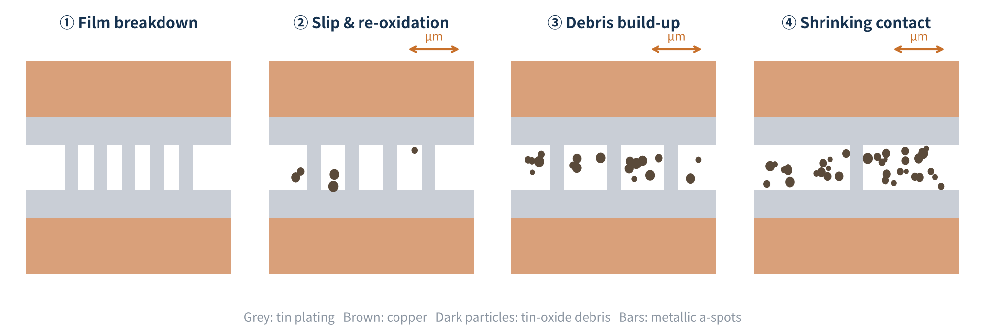
Figure 3 Four stages of fretting corrosion in a tin-plated contact (schematic)
The key variable is contact normal force. With enough force, interface friction locks out the slip — which is exactly how a same-brand pair is designed. Once cross-mating pushes the force toward the bottom of the window, the same temperature swing becomes a larger slip amplitude. Literature shows dry tin contacts beginning to rise in resistance after a few hundred fretting cycles and accelerating after about a thousand. A plant sees about 365 day–night cycles a year from that alone, plus current and temperature swings from passing clouds, so a thousand-plus cycles in three years is no exaggeration — this is the physics behind “contact resistance up tenfold within three years”.
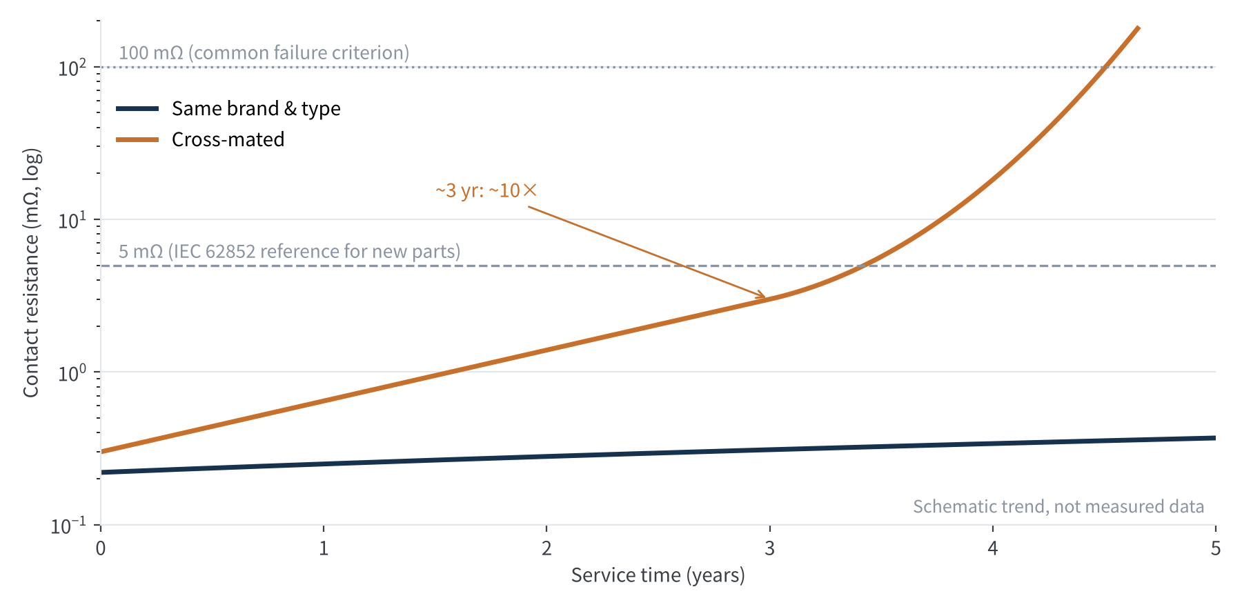
Figure 4 Contact resistance versus service time (schematic)
Bern University of Applied Sciences (BFH), commissioned by Stäubli, sampled connectors in operating plants: within the sample, only cross-mated pairs showed contact resistance above 5 mΩ, the reference limit for new connectors cited from IEC 62852. Given who commissioned it, we treat this as directional evidence, but it is consistent with the mechanism above.
04 From milliohms to fire: the heat budget
Contact resistance itself is tiny; the danger comes from current squared. Taking a string current of about 15 A for today’s large-format modules, heat at the contact is P = I²R:
| Contact resistance | Condition | Heat at contact |
|---|---|---|
| 0.25 mΩ | Maker’s rated maximum | ≈ 0.06 W |
| 2.5 mΩ | 10× increase | ≈ 0.56 W |
| 25 mΩ | 100× increase | ≈ 5.6 W |
| 100 mΩ | Common failure criterion in literature | ≈ 22.5 W |
0.06 W is negligible, but 5 W or more concentrated in a contact spot the size of a grain of rice drives local temperature up fast. Worse, this is a self-accelerating positive feedback loop: higher temperature → faster tin oxidation and stress relaxation of the spring → lower normal force → larger slip and higher resistance → higher temperature. When the plastic housing softens, the seal fails and moisture gets in, an internal arc may form — and a DC arc does not self-extinguish at a zero crossing the way an AC arc does. That is the last step before fire.
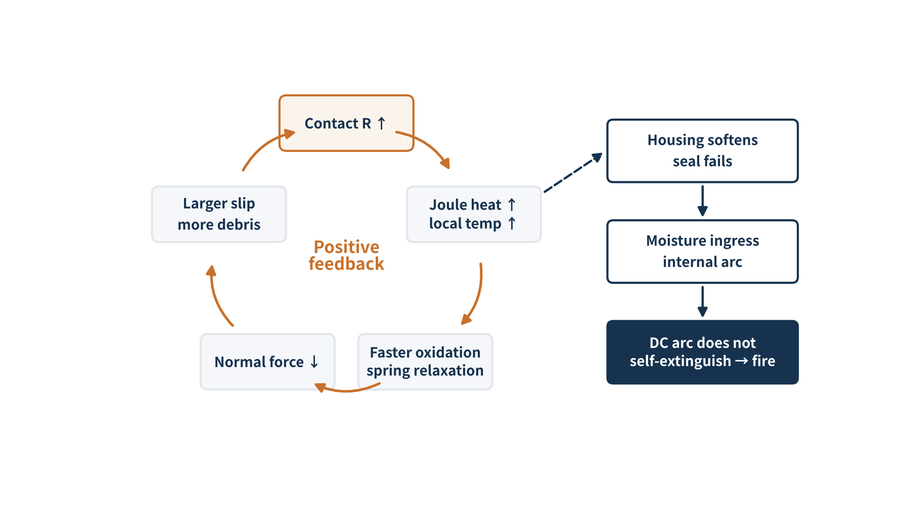
Figure 5 The thermal-runaway feedback loop of rising contact resistance
In one sentence: The risk of cross-mating is not the contact resistance on day one, but the resistance–temperature feedback loop that fretting sets in motion.
05 What the standards say: a compatibility test report is not certification
Strictly speaking, IEC 62852 is a product safety standard: its type tests apply to mated parts of the same type family from one manufacturer, the certificate covers only those combinations, and it no longer applies once brands are cross-mated. The explicit “do not cross-mate” requirement sits in the installation standards — IEC 62548 and IEC 60364-7-712 both require mated plugs and sockets to be of the same type from the same manufacturer. The new edition of IEC 61730-1 also requires the connector type to be marked on the module label so installers can find the right mate. In North America, NEC 2020 Article 690.33(C) permits different brands to be mated only if the combination is listed and identified as intermateable.
There is a counter-view in the market: in 2021 the Dutch solar association Holland Solar commissioned DEKRA to test eight “other brand + original MC4” pairs against selected IEC 62852 test groups, and all passed. The original connector maker’s position is that such one-sided tests cover only part of the test sequences, ignore long-term outdoor effects, and cannot substitute for certification. Our view: standard tests last hundreds of hours, while fretting accumulates over years and cycles, so passing a short-term test does not prove long-term mating reliability. And, more practically, when something goes wrong, liability most likely lands on the installer who made the cross-connection.
06 What to do on the project side: a checklist
- Lock the type at design stage: Specify connector brand and model in the module purchase technical agreement, and select extension cables and combiner/inverter-side mating plugs from that.
- Use adapter leads, not forced mates: A cable may carry different brands at its two ends, as long as every mated plug–socket pair is the same brand and type.
- Match tools to terminals: Use the crimp tool and die specified by the connector maker. Poor crimps are another major failure source, and combined with cross-mating the risk compounds.
- Protect during construction: Cap unmated connectors to keep out water and dirt.
- Targeted O&M inspection: Run thermal imaging on cross-mating hot spots; investigate any clear temperature difference between joints in the same string, and where needed spot-check contact resistance with a micro-ohmmeter against the initial value.
- Fix existing cross-mates properly: Cut one side and re-crimp a matching connector, rather than simply “pushing it in harder”.
07 Final thoughts
Connectors are a tiny share of module BOM cost, yet they carry a whole string’s current for decades. Cross-mating persists not because nobody knows, but because the feedback “it plugs in and works” arrives instantly, while the cost “it wore out and burned” arrives slowly. Treating a connector as a part that is designed as a pair, certified as a pair and used as a pair is the plainest advice we can give from the materials side. Our connector series will go on to cover crimping, sealing and locking — feel free to share cases you have seen in the field.
Calculation notes / data basis
- Displacement estimate: Δx = Δα × ΔT × L = 15×10⁻⁶/K × 60 K × 20 mm ≈ 18 μm. Δα, ΔT and L are typical assumed values; actual figures depend on product design and installation.
- Heat estimate: P = I²R with I = 15 A (order of string operating current for current large-format modules); heat dissipation and the temperature coefficient of resistance are ignored.
- Cycle count: day–night cycles only (about 365 per year); short cycles from cloud cover etc. are not counted, so real cycle numbers are higher.
- Figure 4 is a trend schematic drawn from the fretting-corrosion literature and field experience; it does not represent measured data for any specific product.
References
- IEC 62852:2014+A1:2020, Connectors for DC-application in photovoltaic systems – Safety requirements and tests.
- IEC 62548, Photovoltaic (PV) arrays – Design requirements; IEC 60364-7-712:2017, Solar photovoltaic (PV) power supply systems.
- NFPA 70, National Electrical Code 2020, Article 690.33(C).
- pv magazine. Cross-mating of connectors was chief cause of Netherlands PV fires. 12 April 2019 (TNO investigation).
- Solar Builder. PV connector risks continue to plague solar portfolios (HelioVolta, PV Connectors: The State of the Field). 2025.
- PV Tech / CEA. Grounding issues and damaged modules among most common rooftop solar safety problems (CEA rooftop safety report).
- Bern University of Applied Sciences (BFH). Long-term behaviour of PV connectors (project 2021–2023, commissioned by Stäubli).
- Solar Magazine NL. Testen DEKRA wijzen uit: connectoren 8 fabrikanten kunnen veilig gecombineerd worden met MC4-connectoren. 20 December 2021.
- Stäubli. Statement: Cross-mating of PV connectors – product liability; Stäubli MC4 datasheet (contact resistance ≤ 0.25 mΩ, tin-plated copper, MULTILAM).
- Park Y.W., Sankara Narayanan T.S.N., Lee K.Y. Effect of fretting amplitude and frequency on the fretting corrosion behaviour of tin plated contacts. Surface & Coatings Technology, 2006, 201(6): 2181–2192.
- Park Y.W., Sankara Narayanan T.S.N., Lee K.Y. Fretting corrosion of tin-plated contacts. Tribology International, 2008, 41(7): 616–628.
- Antler M. Contact fretting of electronic connectors. IEICE Trans. Electron., 1999, E82-C(1): 3–12.
- Solar Builder. Wire you doing that? Top four solar installation wire management issues (citing the Solar Bankability FMEA).
PV Materials Lab
PV Materials Lab
A PV R&D and technology team with 10+ years of experience | In-depth technical knowledge sharing
Materials · Reliability · Failure Analysis · Standards & Certification · Products · Processes
Exploring AI + PV — collaboration welcome
Disclaimer:
- Original content reflects the author's personal views only, is for reference, and does not constitute investment advice.
- Reproduced and cited content is attributed to its source, with respect for original work.
- Some content is AI-assisted (chart generation, data retrieval, concept explanations, etc.); the core framework and key content are written by our technical team and reviewed by humans.
- If anything is inaccurate or infringing, please leave a comment or contact us.