
Yellowing, Delamination, Snail Trails, Acetic Acid Corrosion and PID: A Complete Guide to Encapsulant-Related Module Failures
In brief
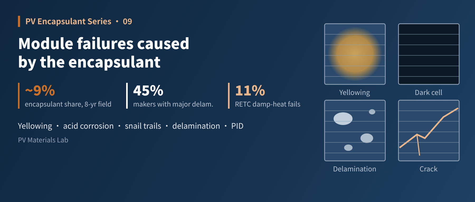
Encapsulant problems usually surface only after a plant has run for several years, and they can hardly be repaired. In this ninth article of our PV encapsulant series, we break down five typical encapsulant-related failures (yellowing, acetic acid corrosion, snail trails, delamination and bubbles, and PID) using a "symptom, mechanism, diagnosis, prevention" structure, and draw on work by IEA PVPS, Fraunhofer and Kiwa PVEL to set out a troubleshooting path from the field to the lab.
At the end of the previous article we said the encapsulant carries a "hidden bill". This article looks at how that bill gets paid.
Encapsulant-related failures share two traits. First, they arrive late, often showing up only after several years of operation. Second, they cannot be fixed: the encapsulant is laminated inside the module, so the only remedy is replacing the whole module. The 2014 IEA PVPS review of module failures cites a field study covering about eight years in which encapsulant failures accounted for about 9%, on a par with burn marks on cells (about 10%). By 2026 the bill has not got any lighter: Kiwa PVEL's reliability scorecard shows that 45% of participating manufacturers had at least one major delamination defect.
01The big picture: which job does each failure map to?
Article 1 described the encapsulant's five jobs. Almost every encapsulant-related failure can be traced back to one of those jobs "breaking down":
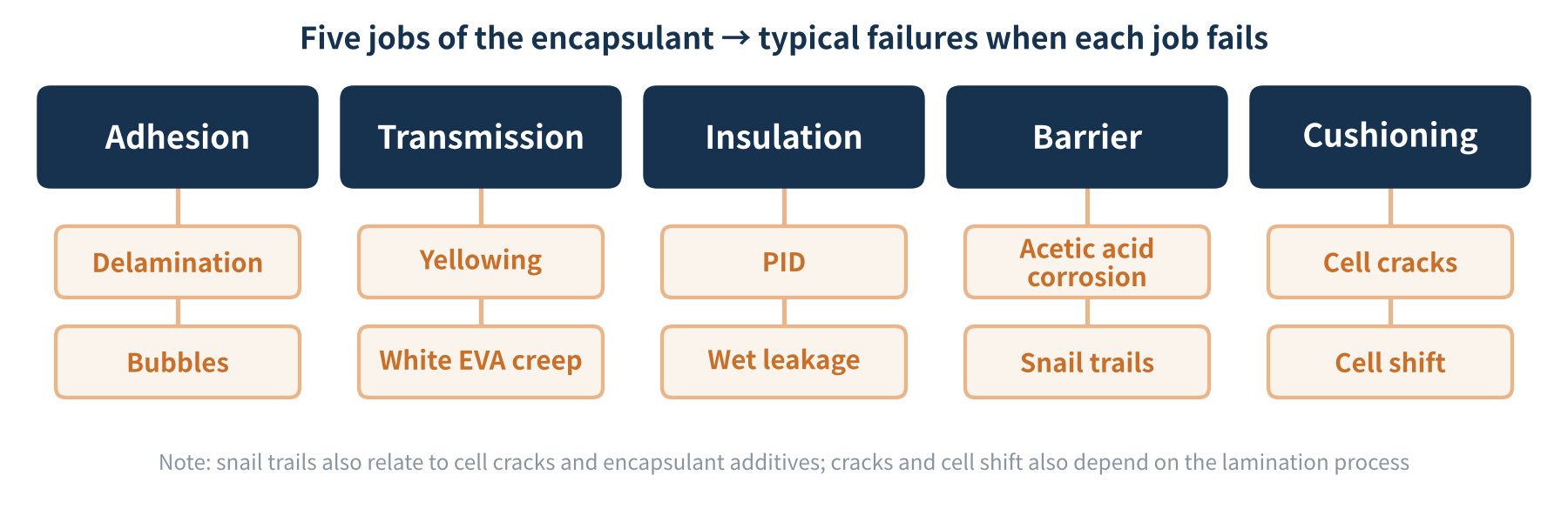
Figure 1 The five jobs of the encapsulant and their typical failures
This mapping matters because it tells you where to look during troubleshooting. Let us take the failures one at a time.
02Yellowing: the most visible form of ageing
- Symptom: The encapsulant over the cells gradually turns yellow or brown. Typically the centre of each cell is darker and the edges lighter, and a light band often runs along cell cracks.
- Mechanism: Under combined UV and heat, the encapsulant resin and its additives (UV absorbers, antioxidants, etc.) gradually form chromophores. The IEA PVPS review notes that photobleaching occurs where the encapsulant has access to atmospheric oxygen, and that near the edges acetic acid can also diffuse out, which produces the "dark centre, light edges" pattern. Cells running hotter (for example in a hot-spot condition) yellow faster.
- Impact: Yellowing reduces transmission, which shows up mainly as a drop in short-circuit current.
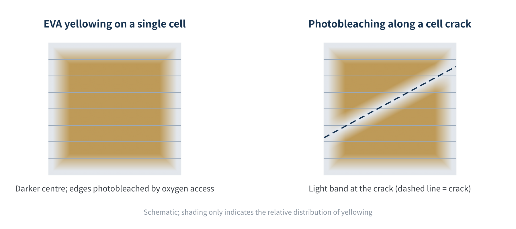
Figure 2 Typical EVA yellowing pattern: dark centre, photobleached edges and cracks
Glass-glass modules deserve a special mention. A 2020 comparison of field-aged modules by Arizona State University (ASU) found that glass-glass modules with EVA showed more severe yellowing, a higher yellowness index, and faster short-circuit current and power degradation. The reason is that glass-glass modules are almost sealed: with no breathable polymer backsheet, photobleaching is limited and volatile degradation products such as acetic acid stay trapped inside. The researchers concluded that EVA may not be a suitable encapsulant for glass-glass modules and that ionomers or polyolefin-type encapsulants are better suited, which explains from the failure side the shift of glass-glass modules to POE/EPE discussed in Article 7.
There is also a newer variable: UV-induced degradation (UVID). TOPCon and HJT cells are more sensitive to UV. A UV-transmitting encapsulant yellows less and gives higher initial power, but it also sends more UV to the cell surface. A 2025 Fraunhofer ISE study concluded that standard UV tests overestimate UVID in TOPCon, yet after light stabilisation some individual modules still lost up to 5%; in RETC's 2026 module index about 8% of models failed the UVID test. The choice of UV cut-off therefore has to weigh encapsulant yellowing against cell UVID.
- Diagnosis: Visual colour difference, UV fluorescence imaging (which clearly shows aged encapsulant areas), and yellowness index and FTIR after dissection.
- Prevention: A sound anti-ageing additive package and UV cut-off design, hot-spot control, and acid-free encapsulants for glass-glass modules.
03Acetic acid corrosion: an invisible chronic disease
- Symptom: The module may look completely normal, but power keeps declining, fill factor drops and series resistance rises; EL images often show dark areas near the fingers or cell edges.
- Mechanism: The vinyl acetate in EVA hydrolyses under damp heat to produce acetic acid, which corrodes the silver fingers and ribbon surfaces and raises contact resistance. In glass-glass modules the acid escapes less easily, so the problem is often worse.
- Diagnosis: I-V curve analysis of series resistance, EL to locate dark areas and, if needed, dissection of the encapsulant with ion chromatography or similar methods to measure acetic acid content.
- Prevention: Use acid-free or low-acid encapsulants such as POE or EPE, or add acid scavengers to EVA; also improve the corrosion resistance of the cell metallisation.
Acetic acid corrosion is one of the most common mechanisms behind power loss after damp heat (DH) testing, and it is why corrosion-sensitive cells such as TOPCon pay particular attention to encapsulant choice. Damp-heat problems have clearly risen in the past two years: in RETC's 2026 module index the share of models failing damp heat rose to about 11% (from about 6% the year before).
Note, however, that not every damp-heat failure is the encapsulant's fault. A 2024 UNSW study found that severe damp-heat failures in HJT and TOPCon modules were closely linked to contact contamination during cell production (sodium, calcium and other ions from gloves, bare hands and suction cups). Contaminated TOPCon modules lost about 15.6% after 1,000 hours of damp heat even with POE. So troubleshooting should put cell surface contamination on the suspect list alongside acetic acid.
04Snail trails: dark lines that "crawl" along cracks
- Symptom: After a few months of operation, dark streaks appear on the cell surface along the fingers or cracks, like the trail left by a snail.
- Mechanism: Fraunhofer CSP's analysis attributes the brownish discolouration to silver nanoparticles that collect in the encapsulant above the fingers, with certain encapsulant additives being the source of these particles. The IEA PVPS review describes snail trails as a discolouration of the silver paste of the fingers that often appears along cell cracks; moisture and oxygen entering through the cracks may take part in the process.
- Impact: The 2014 IEA PVPS review considered the associated power loss not yet clear. In practice the power loss from snail trails themselves is usually limited; their real significance is that they reveal the cracks underneath.
- Diagnosis and prevention: Compare with EL to confirm whether cracks are present, and act on both encapsulant formulation (choice of additives) and crack reduction. Fraunhofer CSP has developed a laboratory method for quickly testing encapsulant films and complete modules for snail-trail susceptibility.
05Delamination and bubbles: when adhesion breaks down
- Symptom: Separation or blistering between the encapsulant and the glass, cells or backsheet, commonly at module edges, around busbars and ribbons, and near the junction box.
- Mechanism: Production-side causes include silane coupling agents degraded by moisture, contaminated glass surfaces and insufficient crosslinking (Articles 4 and 6); in service, adhesion gradually weakens under long-term damp heat and UV.
- Impact: IEA PVPS notes that delamination optically decouples the layers and lowers short-circuit current. More dangerously, if delamination or bubbles form a continuous path between the electrical circuit and the module edge, insulation can fail and create a safety hazard.
- Diagnosis: Visual inspection, pulsed IR thermography (which can tell the depth of bubbles and delamination), and wet leakage current testing.
- Prevention: Store encapsulants protected from moisture, watch peel strength retention after ageing (Article 5), and optimise the lamination profile (Article 6).
Delamination has also become a recurring theme in third-party testing. Kiwa PVEL's 2026 scorecard shows that 45% of participating manufacturers had at least one major delamination defect, and about one third of major delaminations appeared after DH1000/DH2000 damp-heat testing; an improper flux recipe can also cause delamination that spreads from the busbars. The report also lists "thinner encapsulants" among the cost-cutting changes associated with higher failure risk, which is the same point as Article 8: grammage reductions must be validated together with the rest of the module.
06PID: the encapsulant is the first line of defence between voltage and cell
- Symptom: In EL images, modules near the frame or at the high-potential end of a string show some cells completely dark, in a chequerboard pattern; the I-V curve shows lower open-circuit voltage and fill factor.
- Mechanism: A high potential difference drives sodium ions from the glass towards the cell surface, causing shunting. The higher the encapsulant's volume resistivity and the slower the ion migration, the later and milder the PID.
- Diagnosis: EL and I-V testing combined with analysis of system voltage and the module's position in the string. Some PID can be recovered by applying reverse voltage at night.
- Prevention: High-resistivity encapsulants (POE/EPE), anti-PID additives and sound system grounding design.
One update is needed: PID is no longer just the classic "sodium shunting" type. The 2025 IEA PVPS report on failure modes in new cell and module technologies describes a new PID mechanism in HJT modules, so anti-PID assessment in the n-type era cannot simply reuse PERC-era experience. For more on the mechanisms, see our PID series.
07Troubleshooting: from the field to the lab
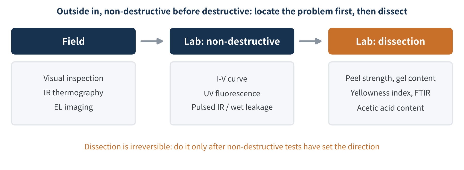
Figure 3 Troubleshooting path for encapsulant-related failures
We recommend troubleshooting encapsulant failures from the outside in and from non-destructive to destructive. First do visual, IR and EL inspections in the field to pinpoint the affected modules and locations; then run I-V and UV fluorescence in the lab to identify the type of degradation; only then dissect, measuring peel strength, gel content, yellowness index, FTIR spectra and acetic acid content. Dissection is irreversible, so do it only after non-destructive tests have set the direction.
| Failure type | Typical symptom | Encapsulant job | Key diagnostic methods |
|---|---|---|---|
| Yellowing | Dark centre, light edges | Transmission | Visual, UV fluorescence, ΔYI, FTIR |
| Acetic acid corrosion | Higher series resistance, EL dark areas | Barrier | I-V, EL, acetic acid content (and rule out cell contamination) |
| Snail trails | Dark streaks along cracks | Barrier / formulation | EL comparison for cracks |
| Delamination / bubbles | Interface separation, blisters | Adhesion | Visual, pulsed IR, wet leakage |
| PID | Chequerboard dark cells | Insulation | EL, I-V, string position analysis |
Table 1 Encapsulant-related failures: symptoms, related jobs and diagnostic methods
Encapsulant failures arrive late and cannot be repaired. When troubleshooting, first identify which job has broken down, then confirm step by step from non-destructive to destructive tests. The work of prevention lies in the previous eight articles.
08Final thoughts
Looking back over these nine articles, from the encapsulant's functions, formulation and processing to testing, lamination, selection and cost, everything points to one question: can the module run stably outdoors for 25 years or more? Failure analysis is the "final review" of that question, and reliability testing is its "mock exam".
In the next article we turn to the encapsulant's role in module reliability testing: which encapsulant capabilities the DH, TC, HF, UV and PID module-level tests actually examine, and how to spot the encapsulant's contribution behind a test failure.
Which problems in your failure analysis have you eventually traced back to the encapsulant? We would be glad to hear from you.
References
- IEA PVPS Task 13: Review of Failures of Photovoltaic Modules (IEA-PVPS T13-01:2014), https://iea-pvps.org/wp-content/uploads/2020/01/IEA-PVPS_T13-01_2014_Review_of_Failures_of_Photovoltaic_Modules_Final.pdf
- Patel A.P., Sinha A., TamizhMani G.: Field-Aged Glass/Backsheet and Glass/Glass PV Modules: Encapsulant Degradation Comparison, IEEE Journal of Photovoltaics, 10(2), 607–615 (2020), https://asu.elsevierpure.com/en/publications/field-aged-glassbacksheet-and-glassglass-pv-modules-encapsulant-d
- Fraunhofer CSP: Rapid Laboratory Test Method for Snail Trails, https://csp.fraunhofer.de/en/areas-of-research/diagnostics-metrology-solar-cells/highlights/Laboratory-Test-Snail-Trails.html
- IEA PVPS Task 13: Assessment of Photovoltaic Module Failures in the Field (IEA-PVPS T13-09:2017), https://iea-pvps.org/key-topics/report-assessment-of-photovoltaic-module-failures-in-the-field-2017/
- IEA PVPS Task 13: Degradation and Failure Modes in New Photovoltaic Cell and Module Technologies (IEA-PVPS T13-30:2025), https://iea-pvps.org/wp-content/uploads/2025/02/IEA-PVPS-T13-30-2025-EX-SUMM-Degradation-and-Failure.pdf
- Kiwa PVEL: 2026 Scorecard failures (EU PVSEC 2026), https://www.kiwa.com/globalassets/us/pvel/news/kiwa-pvel-2026-eupvsec-scorecard-failures.pdf.pdf
- Solar Power World: Latest PV module reliability scorecard shows unsettling uptick in failures, May 2026, https://www.solarpowerworldonline.com/2026/05/latest-pv-module-reliability-scorecard-shows-unsettling-uptick-in-failures/
- pv magazine USA: Latest RETC solar module quality report reveals significant issues, 3 June 2026, https://pv-magazine-usa.com/2026/06/03/latest-retc-solar-module-quality-report-reveals-significant-issues/
- TaiyangNews: TOPCon UVID: Less Severe Than Assumed (Fraunhofer ISE), 15 April 2025, https://taiyangnews.info/technology/fraunhofer-ise-uvid-uv-stabilization-topcon
- Sen C. et al.: Hidden Fingerprints: How Solar Cell Handling Leads to Damp Heat Failures in HJT and TOPCon Modules, APVI Solar Research Conference, 2024, https://apvi.org.au/solar-research-conference/wp-content/uploads/2024/12/Sen_C_Hidden_Fingerprints_How_Solar_Cell_Handling_Leads_to_Damp_Heat_Failures_in_HJT_and_TOPCon_Modules.pdf
- T/CPIA 0071—2024, Co-extruded Encapsulant Films for PV Modules (光伏组件封装用共挤胶膜), China Photovoltaic Industry Association
A PV R&D and technology team with 10+ years of experience | In-depth technical knowledge sharing
Materials · Reliability · Failure Analysis · Standards & Certification · Products · Processes
Exploring AI + PV; collaboration welcome
Disclaimer:
1. Original content reflects the authors' personal views only, is for reference only and does not constitute investment advice.
2. Reposted and cited content is credited to its source, out of respect for original work.
3. Some content was produced with AI assistance (chart generation, data retrieval, concept explanations, etc.); the core framework and key content were written by our technical team and reviewed by people.
4. If anything is inaccurate or infringes your rights, please leave a message or contact us and we will deal with it.