
DH, TC, HF, UV, PID: What Do Module Reliability Tests Really Ask of the Encapsulant?
In brief
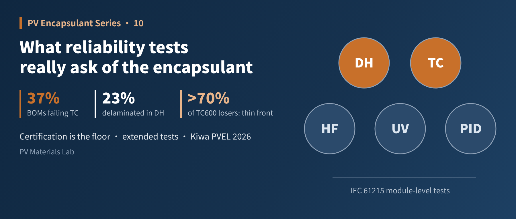
Article 5 covered material-level ageing of encapsulants; this one covers module-level reliability testing, where the encapsulant is tested inside a complete module together with cells, ribbons, glass and backsheet. In this tenth article of our PV encapsulant series, we go through the damp heat, thermal cycling, humidity freeze, UV and PID tests of IEC 61215 and the encapsulant job each one examines, then use the encapsulant-related findings of the Kiwa PVEL 2026 Reliability Scorecard to discuss why passing certification does not mean reliable, and how to judge the encapsulant's share of blame after a test failure.
In Article 5 we looked at material-level ageing: on simplified laminate coupons, we assessed peel strength and yellowing after ageing. But the encapsulant ultimately has to work inside a module, enduring temperature, humidity, UV and voltage together with cells, ribbons, glass, backsheet and frame.
In this article we look at module-level reliability testing: what each test is really asking of the encapsulant, and, after a failure, how to tell whether the encapsulant is to blame.
01Two kinds of "exam": material level and module level
- Material-level ageing (Article 5): The sample is a simplified laminate, the criteria are peel strength and yellowness index, and the purpose is to screen the encapsulant itself.
- Module-level testing (this article): The sample is a complete module tested to IEC 61215 and similar standards; the main criteria are power loss (generally no more than 5% per test sequence), visual defects, insulation and wet leakage.
The difference lies in interactions. An encapsulant that performs well at material level can still fail inside a module, because it must work together with the cell metallisation, ribbon stress, glass edges and backsheet moisture permeability. Module-level tests examine not the encapsulant's stand-alone performance but how it performs within the system.
02One table: which encapsulant job each test examines
| Test | Typical conditions (IEC 61215) | Main encapsulant jobs examined | Typical encapsulant-related failures |
|---|---|---|---|
| Damp heat DH | 85 °C / 85% RH, 1,000 h | Barrier, adhesion, hydrolysis resistance | Acetic acid corrosion, delamination, yellowing |
| Thermal cycling TC | −40 °C to +85 °C, 200 cycles | Cushioning, adhesion | Solder joint fatigue, cell cracks, delamination |
| Humidity freeze HF | 85 °C/85% RH alternating with −40 °C, 10 cycles | Adhesion | Delamination, bubbles |
| UV preconditioning | 280–400 nm, 15 kWh/m² | Transmission, ageing resistance | Yellowing, loss of adhesion |
| Potential-induced degradation PID | 85 °C/85% RH, system voltage, 96 h | Insulation | PID power loss |
Table 1 Main IEC 61215 tests and their relation to the encapsulant
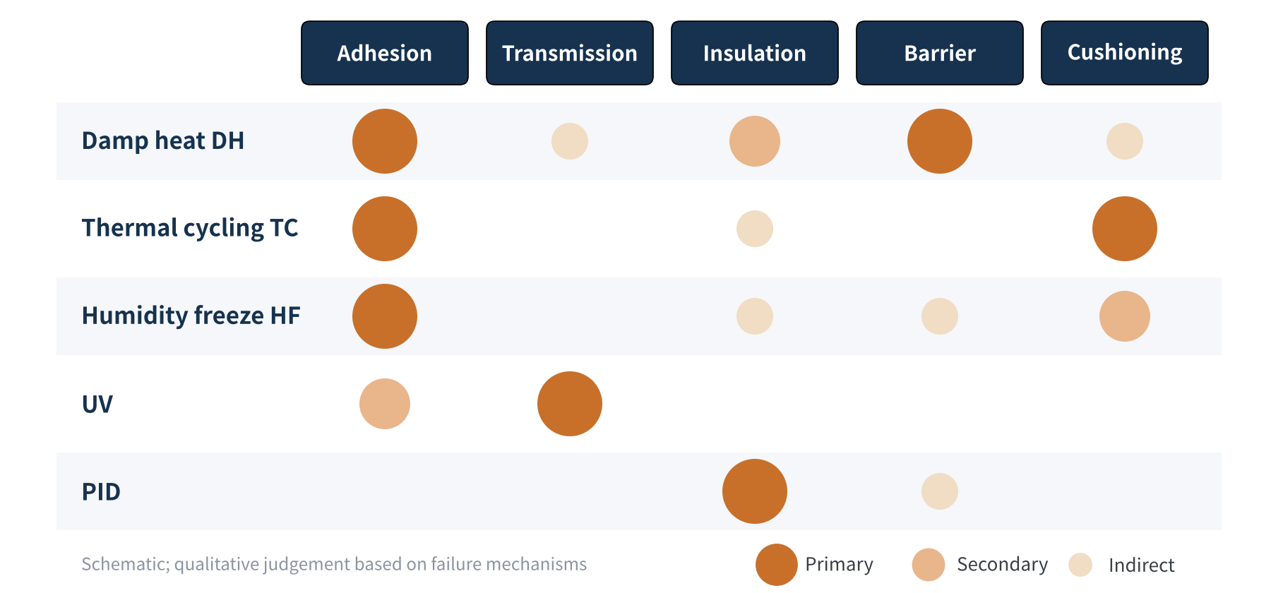
Figure 1 Strength of the link between module reliability tests and the five jobs of the encapsulant (schematic)
Almost every test involves the encapsulant, but each with a different emphasis. Below we expand on the most important ones.
03Damp heat DH: the encapsulant's main exam
1,000 hours at 85 °C and 85% RH is the most direct test of the encapsulant's barrier and hydrolysis resistance. Moisture keeps permeating into the module, EVA hydrolyses into acetic acid that corrodes fingers and ribbons, and damp heat keeps weakening the bond between encapsulant and glass or backsheet.
Kiwa PVEL's 2026 Module Reliability Scorecard reports that 32% of tested BOMs had at least one damp-heat failure, including 23% of BOMs with a delamination failure; another 6% of BOMs already delaminated during initial characterisation. In Kiwa PVEL's failure analysis, delamination accounts for 46% of visual inspection failures, which in turn make up 73% of all failures. Damp-heat delamination has become a prominent module reliability problem.
Why is delamination an outright failure? Delamination and bubbles at the edge of glass-glass modules shorten the creepage distance from the circuit to the module edge; once it falls below the IEC 61730 minimum (10.4 mm for 1,500 V modules), it is a major defect. Kiwa PVEL described a DH2000 case in which two BOMs from the same manufacturer, using two different encapsulants, both delaminated extensively and creepage fell to 0 mm.
Kiwa PVEL's preliminary analysis presented at EU PVSEC 2026 contains several points that encapsulant practitioners should note:
- Encapsulant type: Using EPE as both front and rear encapsulant triggered the largest number of major defects.
- Encapsulant width: The narrower the encapsulant, the higher the failure rate.
- Solder flux: An improper flux recipe can cause delamination that spreads from the string busbars.
- Unexpected negatives: Thinner encapsulant did not show a higher damp-heat delamination risk; lamination temperature and time were not the main drivers; and gel content and peel force were not direct predictors of delamination.
As the UNSW study cited in Article 7 showed, however, not every damp-heat failure is the encapsulant's fault: contact contamination of cells during production can also cause severe degradation. Troubleshooting has to look at both sides.
04Thermal cycling TC: a fatigue test of cushioning and adhesion
Cycling repeatedly between −40 °C and +85 °C, the different thermal expansion coefficients of glass, silicon and copper ribbon create stress in every cycle. As Article 1 explained, the encapsulant, as the flexible middle layer, "absorbs" this stress; if the layer is too thin, its modulus is unsuitable or it stiffens at low temperature, more stress is passed to the solder joints and cells, causing solder joint fatigue, cell cracks and power loss.
The Kiwa PVEL 2026 Scorecard contains a finding directly related to the encapsulant: 37% of BOMs failed thermal cycling, a record high; and more than 70% of BOMs with over 2% power loss after TC600 used front encapsulant in the lower quartile of area weight (no more than 400 g/m²).
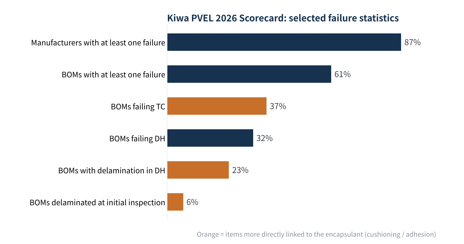
Figure 2 Selected failure statistics from the Kiwa PVEL 2026 Reliability Scorecard (source: Kiwa PVEL)
This echoes the warning in Article 8: grammage reduction has limits. If the front encapsulant is made too thin, the fraction of a cent saved may be "paid back" several times over in thermal cycling. Notably, thin encapsulant did not show a higher risk of damp-heat delamination; its weakness is mainly in cushioning rather than adhesion, which shows that different tests really do examine different jobs.
05Humidity freeze HF and UV: two easily underestimated tests
- Humidity freeze HF: The module first absorbs moisture at 85 °C and 85% RH, then is rapidly cooled to −40 °C. Water that has entered interfaces and small defects freezes and expands, a "frost heave" test of adhesion; modules with incomplete lamination, micro-bubbles or weak adhesion are more likely to delaminate here.
- UV: The UV preconditioning dose in IEC 61215 is only 15 kWh/m². It mainly checks how UV affects subsequent tests and is far too low to expose UV-induced degradation (UVID).
This is why third-party labs run separate UVID tests. Kiwa PVEL uses a dose of 120 kWh/m². Its 2026 Scorecard shows the median UVID power loss of TOPCon modules falling from 4.2% the previous year to 3.0%, and the share of BOMs failing UVID falling from 6% to 3%; after one year of outdoor exposure in Davis, California, modules showed a median degradation of about 2% and a maximum of about 8%.
One test detail also deserves attention: some TOPCon modules show dark-storage degradation of up to about 1% power loss per day. How long a module sits before its power is measured directly affects the result, so UV-related data must be interpreted with particular care.
Standards are catching up. A 2026 study by Fraunhofer ISE and Fraunhofer CSP in EPJ Photovoltaics showed that a light-stabilisation step is needed after UV testing to remove dark-storage effects, a procedure also cited in support of the draft IEC TS 63624-1; with stabilisation, indoor UV tests correlate well with outdoor degradation, only slightly overestimating it for TOPCon. The study also recommends counting only UV below 365 nm for TOPCon UVID dosing: in its setup, a conventional dose of 60 kWh/m² (≤400 nm) corresponded to about 44 kWh/m² (≤365 nm). In other words, two UV tests that both quote "X kWh/m²" are not necessarily comparable between labs.
06PID: a direct test of insulation
IEC 61215:2021 made the PID test a standard test item (MQT 21). Following the damp-heat stress method of IEC TS 62804-1, system voltage is applied to the module at high temperature and humidity; if the module is specified only for systems with one terminal earthed, only that polarity is tested, otherwise both polarities are. This test directly examines the "insulation" job described in Article 1: the higher the encapsulant's volume resistivity and the slower the ion migration, the better the module resists PID. Kiwa PVEL's extended test doubles the duration to 192 hours and covers both PID(+) and PID(−).
07Certified is not the same as reliable: why extended testing matters
IEC 61215 is the pass mark for entering the market, not the ceiling of reliability. To get closer to 25+ years of outdoor service, third-party labs and plant owners often use extended tests:
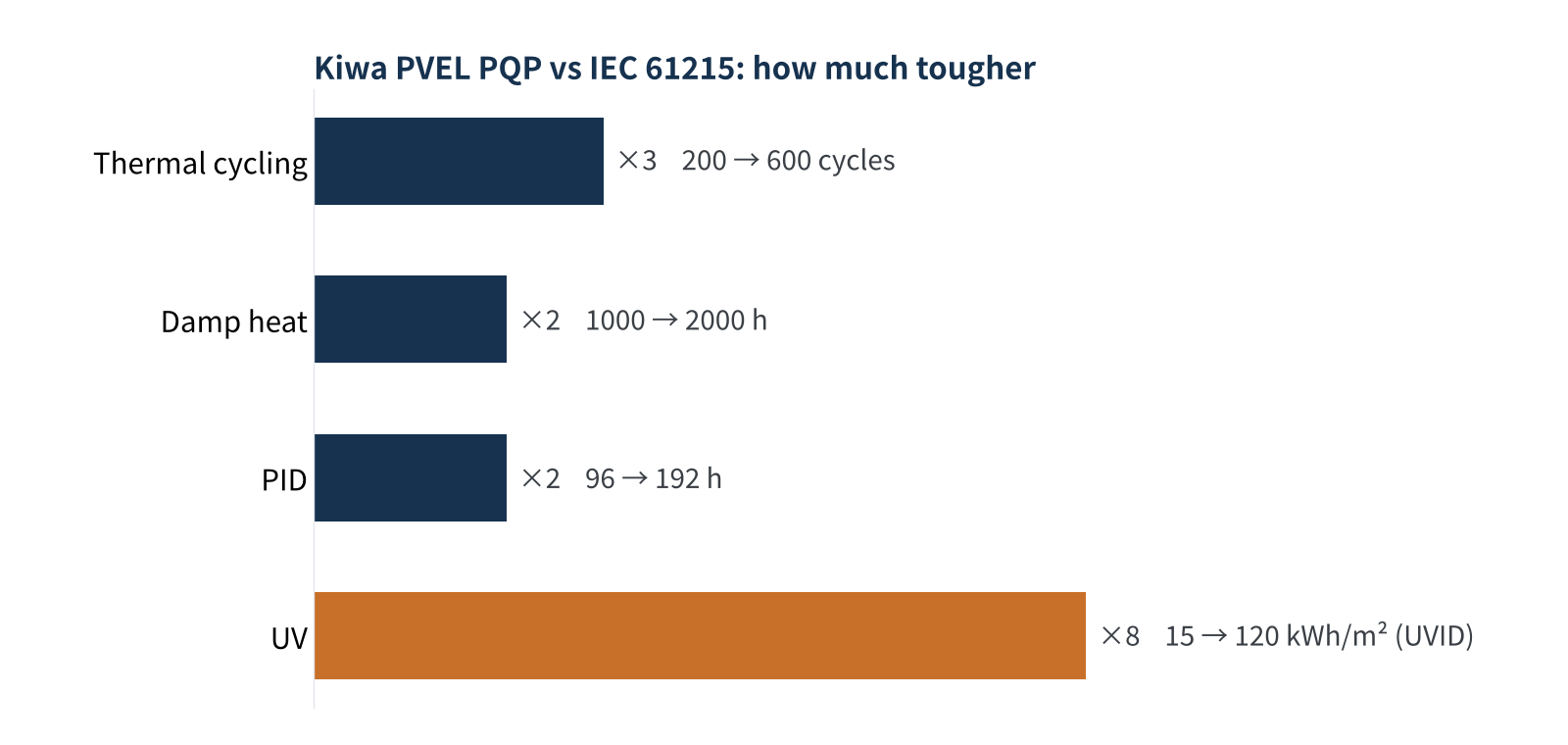
Figure 3 Key test durations: IEC 61215 vs Kiwa PVEL PQP
In the Kiwa PVEL 2026 Scorecard, 87% of module manufacturers and 61% of BOMs had at least one test failure, up from 83% and 59% the year before. Two more encapsulant-related findings deserve attention:
- Front encapsulant type: BOMs using EPE or POE as the front encapsulant had a higher rate of both major and minor delamination than BOMs using EVA. This is a reminder that POE-type encapsulants are good water barriers but adhesion is their weak point (Article 2).
- Encapsulant width: When the encapsulant is narrower than the glass, delamination is more likely. The edge is both the entry path for moisture and the weakest point of adhesion; in glass-glass modules, a lack of encapsulant along the edges has also been linked to glass breakage.
08Reading test failures from the encapsulant's side
- Start with the type of loss: A drop mainly in short-circuit current points to optical causes (yellowing, delamination); higher series resistance and lower fill factor point to corrosion; simultaneous drops in open-circuit voltage and fill factor with shunting suggest PID.
- Then look at where it fails: Damage that spreads from the edges inward is usually related to moisture and acetic acid paths; damage along ribbons and busbars is usually related to stress, adhesion or flux residues.
- Compare with material-level data: Only by setting module test results against the encapsulant's gel content, peel strength retention, water vapour transmission rate and resistivity can you tell whether the problem lies in the encapsulant itself or in matching, process or cells. But note that Kiwa PVEL's preliminary analysis found gel content and peel force are not direct predictors of delamination, so a single material indicator being "in spec" does not clear the encapsulant.
- Watch the test details: Storage time after testing, light preconditioning and how the UV dose is counted can all affect power readings.
Module-level tests examine how the encapsulant performs within the system. Certification is the pass mark, and extended tests are closer to real service life; reading a failure correctly means looking at the type of loss, where it occurs and the material data together.
09Final thoughts
Reliability testing is the bridge between the lab and the power plant. The 2026 PVEL Scorecard findings on front encapsulant grammage, EPE/POE delamination and encapsulant width tie together the formulation, processing, cost reduction and failures covered in earlier articles: every encapsulant choice eventually leaves its mark in the test chamber.
Once testing is done, everything comes down to purchasing and qualification. In the next article we take the buyer's view: encapsulant selection, qualification and incoming inspection — what to verify when introducing a new encapsulant, how material certification relates to BOM certification, and the most common pitfalls when changing encapsulants.
What encapsulant-related failures have you met in module certification or extended testing? We would be glad to hear from you.
References
- IEC 61215-1/-2:2021 Terrestrial photovoltaic (PV) modules – Design qualification and type approval
- IEC TS 62804-1 Photovoltaic (PV) modules – Test methods for the detection of potential-induced degradation
- Kiwa PVEL: 2026 PV Module Reliability Scorecard – Executive Summary, https://www.kiwa.com/globalassets/germany/downloads-temporary/intersolar-2026/2026-pv-module-reliability-scorecard-executive-summary-1.pdf
- Kiwa PVEL: Exploring the rise of PV module failures and their potential causes (2026), https://www.kiwa.com/globalassets/us/pvel/resources/2026-kiwa-pvel----exploring-the-rise-of-pv-module-failures-and-their-potential-causes.pdf
- Kiwa PVEL: 2026 Scorecard failures (EU PVSEC 2026), https://www.kiwa.com/globalassets/us/pvel/news/kiwa-pvel-2026-eupvsec-scorecard-failures.pdf.pdf
- Kiwa PVEL: Product Qualification Program (PQP) / UV-Induced Degradation, https://www.kiwa.com/pvel/pqp/uvid
- Gebhardt P. et al.: UV-induced degradation: comparative analysis of PV module testing and stabilization procedures against outdoor behavior, EPJ Photovoltaics 17, 15 (2026), https://www.epj-pv.org/10.1051/epjpv/2026007
- Sinovoltaics: IEC 61215 MQT 21: Potential Induced Degradation (PID) Test for Solar Modules, https://sinovoltaics.com/learning-center/testing/iec-61215-mqt-21-potential-induced-degradation-pid-test-for-solar-modules/
- Sen C. et al.: Hidden Fingerprints: How Solar Cell Handling Leads to Damp Heat Failures in HJT and TOPCon Modules, APVI Solar Research Conference, 2024, https://apvi.org.au/solar-research-conference/wp-content/uploads/2024/12/Sen_C_Hidden_Fingerprints_How_Solar_Cell_Handling_Leads_to_Damp_Heat_Failures_in_HJT_and_TOPCon_Modules.pdf
A PV R&D and technology team with 10+ years of experience | In-depth technical knowledge sharing
Materials · Reliability · Failure Analysis · Standards & Certification · Products · Processes
Exploring AI + PV; collaboration welcome
Disclaimer:
1. Original content reflects the authors' personal views only, is for reference only and does not constitute investment advice.
2. Reposted and cited content is credited to its source, out of respect for original work.
3. Some content was produced with AI assistance (chart generation, data retrieval, concept explanations, etc.); the core framework and key content were written by our technical team and reviewed by people.
4. If anything is inaccurate or infringes your rights, please leave a message or contact us and we will deal with it.