
Junction Box Series 4 | Connectors and Cables: Where Do PV Plant Fires Really Start?
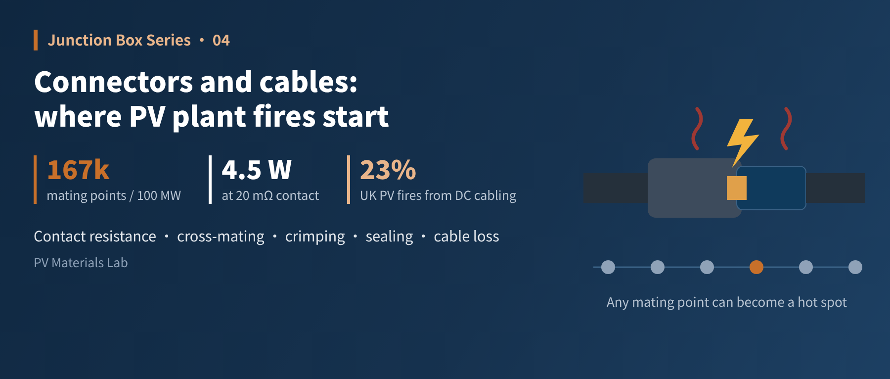
In brief
Contact resistance, cross-mating and crimp quality — a close look at the three critical interfaces of PV connectors, and the easily overlooked losses and hazards of PV cables. This is the fourth article of our junction box series and the last of its "fundamentals" part.
The previous three articles dealt with what happens inside the box. This one steps outside it to look at the two most inconspicuous yet most failure-prone items: connectors and cables.
A junction box is assembled, inspected and certified in a factory under full control; but the final step for a connector — mating — is done on site by installers. It is the only electrical connection in the whole DC circuit that is made by plugging in, and made in the field.
So this article answers: why does a small plug become a hot spot for plant fires?
01First, the numbers: quantity drives risk
Take a 100 MW plant with 600 W modules: number of modules = 100,000,000 ÷ 600 ≈ 167,000. With one mating point between each module and its neighbour, the plant has well over a hundred thousand — before counting the inverter and combiner box side.
These hundred-thousand-plus mating points are all in series within their circuits. If any one has a poor contact, the whole string's current has to squeeze through it.
Worse still is the nature of direct current. Alternating current passes through zero every cycle, so arcs tend to extinguish themselves; direct current has no zero crossing, so once a loose contact draws an arc, it keeps burning at temperatures of thousands of degrees — enough to ignite the plastic housing and nearby combustibles.
Over a hundred thousand mating points in series, plus DC arcs that do not self-extinguish — that is why connectors must be taken seriously.
Two 2026 statistics bear this out. A survey of UK fire services by insurer QBE found 212 PV-related fires in Great Britain in 2025, of which 49 (about 23%) were attributed to DC cabling and plug connections — the largest single category; relative to the installed base, the fire rate was still below 0.07 per 1,000 systems. A multi-country study published in Fire Safety Journal likewise found that in Sweden, where the data are most detailed, DC cables and connectors were the most common ignition source, at roughly one quarter of incidents. PV fires remain rare overall, but when one happens, the connections are the first place to look.
02Taking it apart: three critical interfaces
A mated connector pair contains three interfaces that decide success or failure:
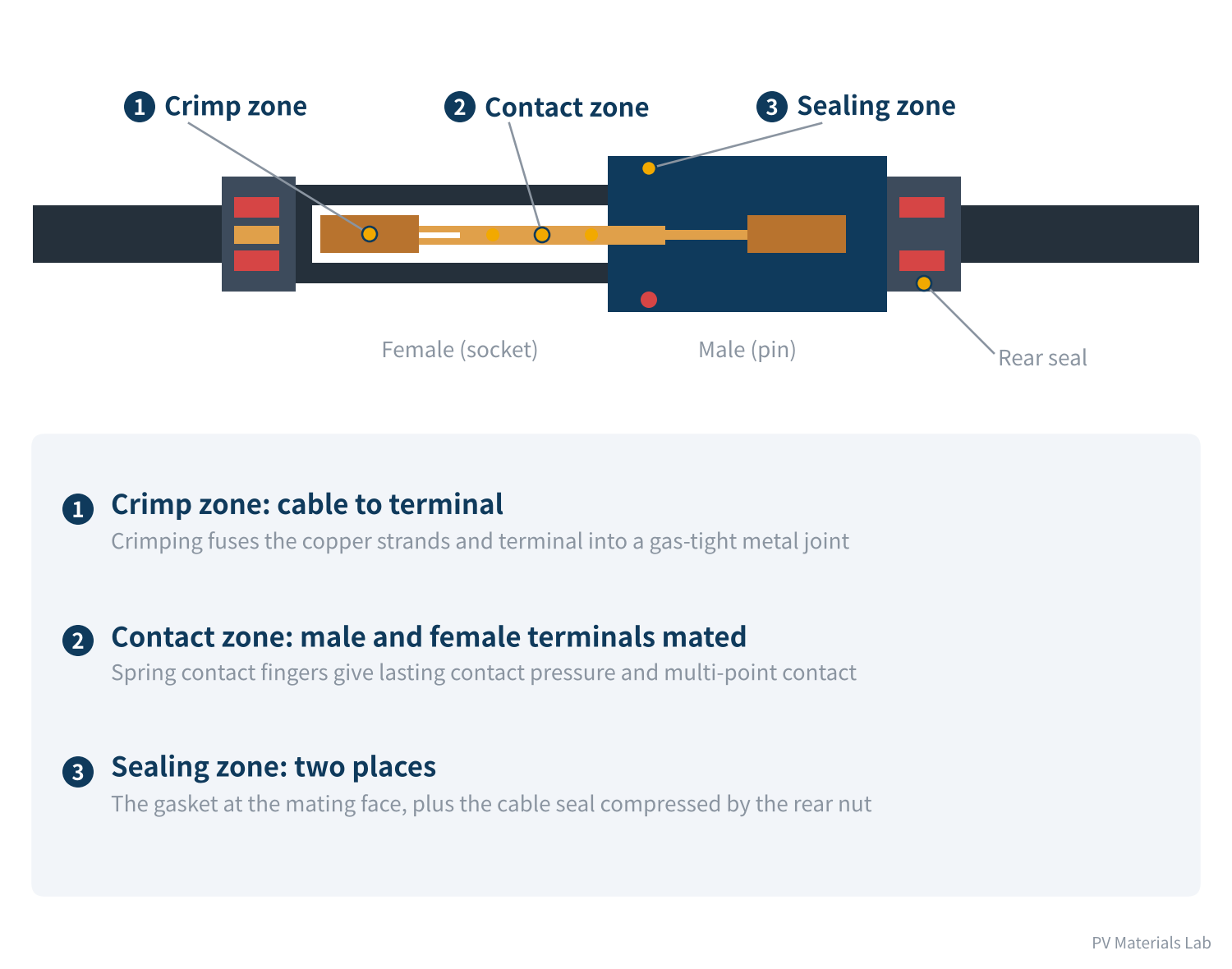
Figure 1 Connector cross-section: three critical interfaces
- Crimp zone: Between the cable's copper strands and the metal terminal, joined by crimping.
- Contact zone: Between the male pin and female socket, with pressure maintained by spring contact fingers.
- Sealing zone: One at the mating face, relying on a gasket; one at the rear, where a nut compresses the cable seal.
The first two interfaces determine resistance; the third determines whether the first two can last. Let us take them one at a time.
03The contact zone: where contact resistance comes from
To the naked eye, the pin and socket touch across their whole surface. At the microscopic scale, however, even the smoothest metal surface is rough, and current actually flows through only a few tiny spots.
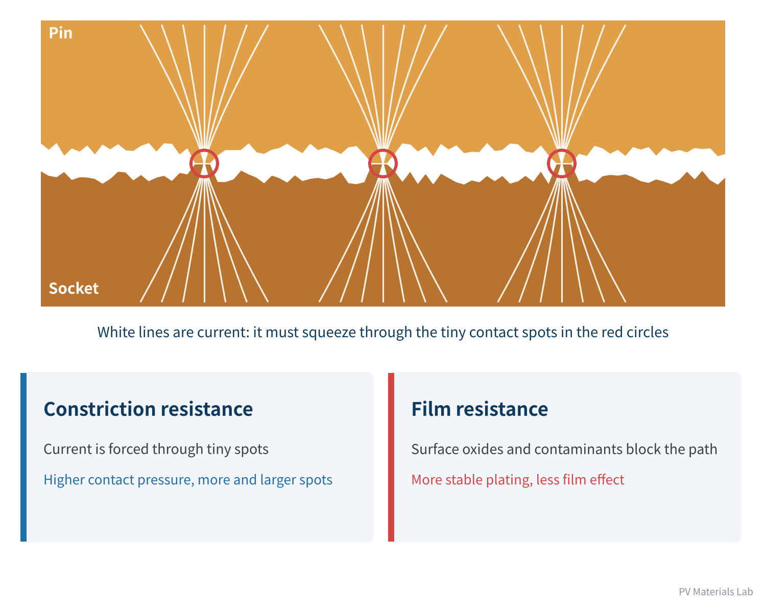
Figure 2 A close-up of the contact surface: current flows through just a few "spots"
Contact resistance has two components:
- Constriction resistance: Current is forced from a wide conductor into tiny contact spots. The higher the contact pressure, the more and larger the spots and the lower the resistance.
- Film resistance: Oxide films and contaminants on the metal surface block the current path. The more stable the plating and the cleaner the surface, the lower the resistance.
Connector design therefore comes down to two things: spring contact fingers that provide sufficient and lasting contact pressure, and plating (tin or silver) that protects the contact surface.
How it deteriorates
A good connector's contact resistance is usually below 0.5 mΩ when new, with negligible heating. The problem is that it degrades over time:
| Mechanism | What happens | Triggers |
|---|---|---|
| Stress relaxation | Contact fingers lose spring force under long-term heat, reducing contact pressure | High temperature, unsuitable material |
| Fretting wear | Day–night temperature swings and wind sway cause repeated micro-movement that wears through the plating | Unsecured cables, thermal expansion and contraction |
| Oxidation and corrosion | Moisture, salt spray etc. get in and non-conductive corrosion products form on the contact | Seal failure, harsh environments |
Table 1 Three degradation mechanisms of contact resistance
At 15 A, the heat at a single contact is P = I²R:
At 0.3 mΩ, about 0.07 W — not even warm to the touch;
degraded to 5 mΩ, about 1.1 W — the connector is clearly hot;
degraded to 20 mΩ, 4.5 W — enough to soften and deform the plastic housing.
The heat in turn accelerates stress relaxation and oxidation, forming the vicious circle described in the first article. Contact resistance does not degrade linearly; the further it goes, the faster it gets.
04Cross-mating: the most common human-made risk
"They are all MC4, so they should be interchangeable, right?" — the most common and most dangerous sentence heard on site.
"MC4" was originally a product model of one manufacturer (Multi-Contact, now Stäubli), not an industry interface standard with unified dimensions and tolerances. Many "compatible" connectors on the market simply look similar and can be pushed together.
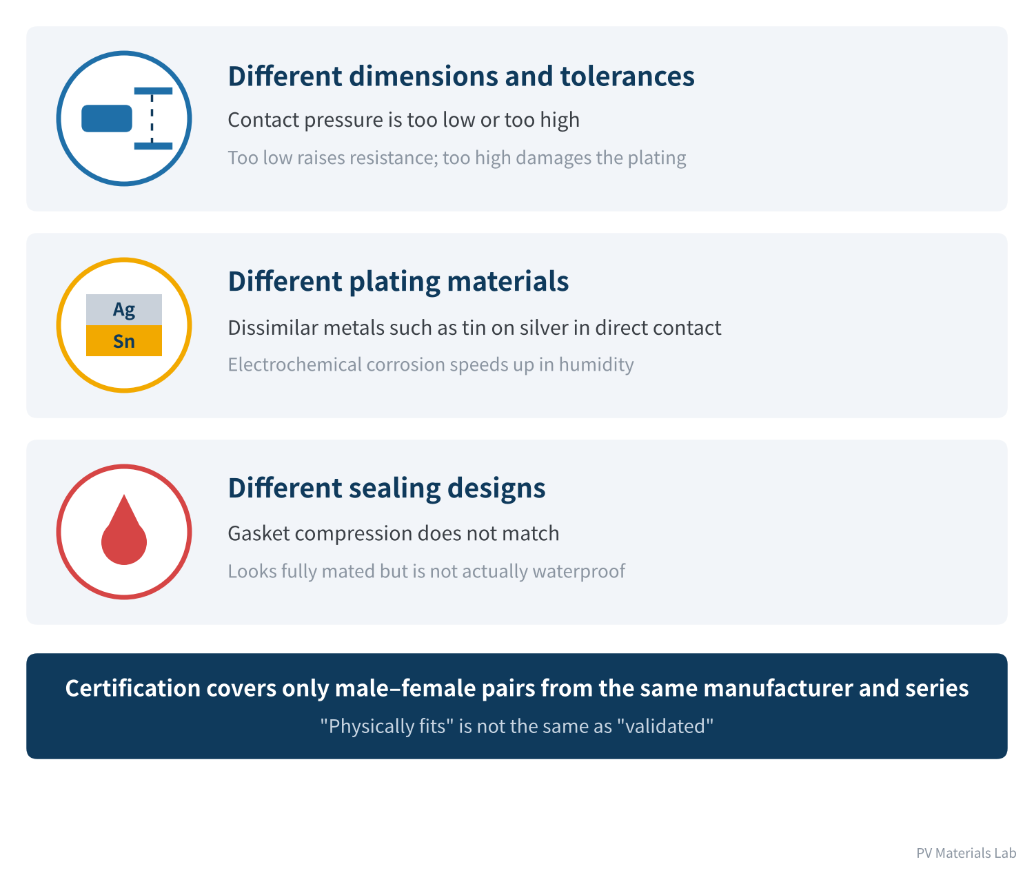
Figure 3 Three types of hazard when mating connectors of different brands
The same applies to certification. The connector safety standard IEC 62852:2014+A1:2020 (and UL 6703 in the US) tests male–female pairs of the same manufacturer and type family. No product certification covers a combination of two brands, and third-party "cross-mating tests" are not certification either. The PV array design standard IEC 62548:2016 explicitly requires that connectors mated together be of the same type from the same manufacturer; that standard has been replaced by IEC 62548-1:2023, with Amendment 1 published in 2025, and new projects should be designed to the new edition.
Where cross-mating typically happens
- Between modules and extension cables: Modules come with one brand of connector, while the installer buys extension cables with another.
- Between strings and inverters or combiner boxes: Device-side connectors are supplied by the equipment maker and differ from the module side.
- During O&M replacement: One fails, and whatever is at hand on site goes in.
When cross-mating causes a problem, the module maker says the connectors were mixed, the connector maker says the combination was never validated, and the installer says both brands were certified. Beyond the technical risk, warranty and liability become a muddle. The safest approach is to lock in the same manufacturer and model at the purchasing stage.
05The crimp zone: quality you cannot see
When modules leave the factory, the crimp between cable and connector terminal is done by automated equipment with assured consistency. The risk lies mainly in field crimping — extension and home-run cables are made on site.
A good crimp is not just "clamped tight"; it deforms the copper strands and terminal plastically until no gaps remain, forming a gas-tight whole that moisture and oxygen cannot enter.
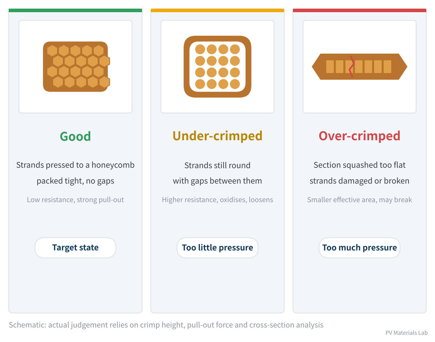
Figure 4 Crimp cross-sections: good, under-crimped and over-crimped
Crimp quality depends on four factors:
- Dedicated crimping tool: The die must match the terminal model and wire size. Pliers or generic crimpers are the classic source of field incidents.
- Strip length: Too short gives an insufficient crimp; too long leaves copper exposed.
- Intact strands: No strands may be cut during stripping, and no stray strands may sit outside the crimp barrel.
- No insulation in the crimp: Insulation pressed into the crimp barrel causes local poor contact.
There are three ways to verify: measuring crimp height, testing pull-out force, and cross-section analysis. The first two suit field sampling; the third suits first-article approval and problem analysis.
06The sealing zone and installation: six common pitfalls
Connectors are usually rated IP68, but with one condition: only after correct mating with the nut tightened. Many failures are seeded when that condition is not met.
- Rain and sand before mating: Unmated connectors are not waterproof. If modules sit on site overnight with connectors exposed to rain, and water and sand get in before mating, the hazard is sealed inside.
- Not fully mated: Assuming the connector is mated without hearing the latch click, leaving insufficient contact length.
- Rear nut not tightened: The cable seal is incomplete and water seeps along the cable. Tighten to the manufacturer's specified torque.
- Connector under strain or hanging free: With cables unsecured, connectors are pulled and swayed by wind over the long term, accelerating fretting wear.
- Submerged or lying on the ground: Connectors left in purlin channels or roof puddles are soaked for long periods.
- Contact with chemicals: Lubricants, cleaners and anti-corrosion coatings can cause stress cracking of plastic housings; check compatibility before use.
07Cables: underestimated losses and hazards
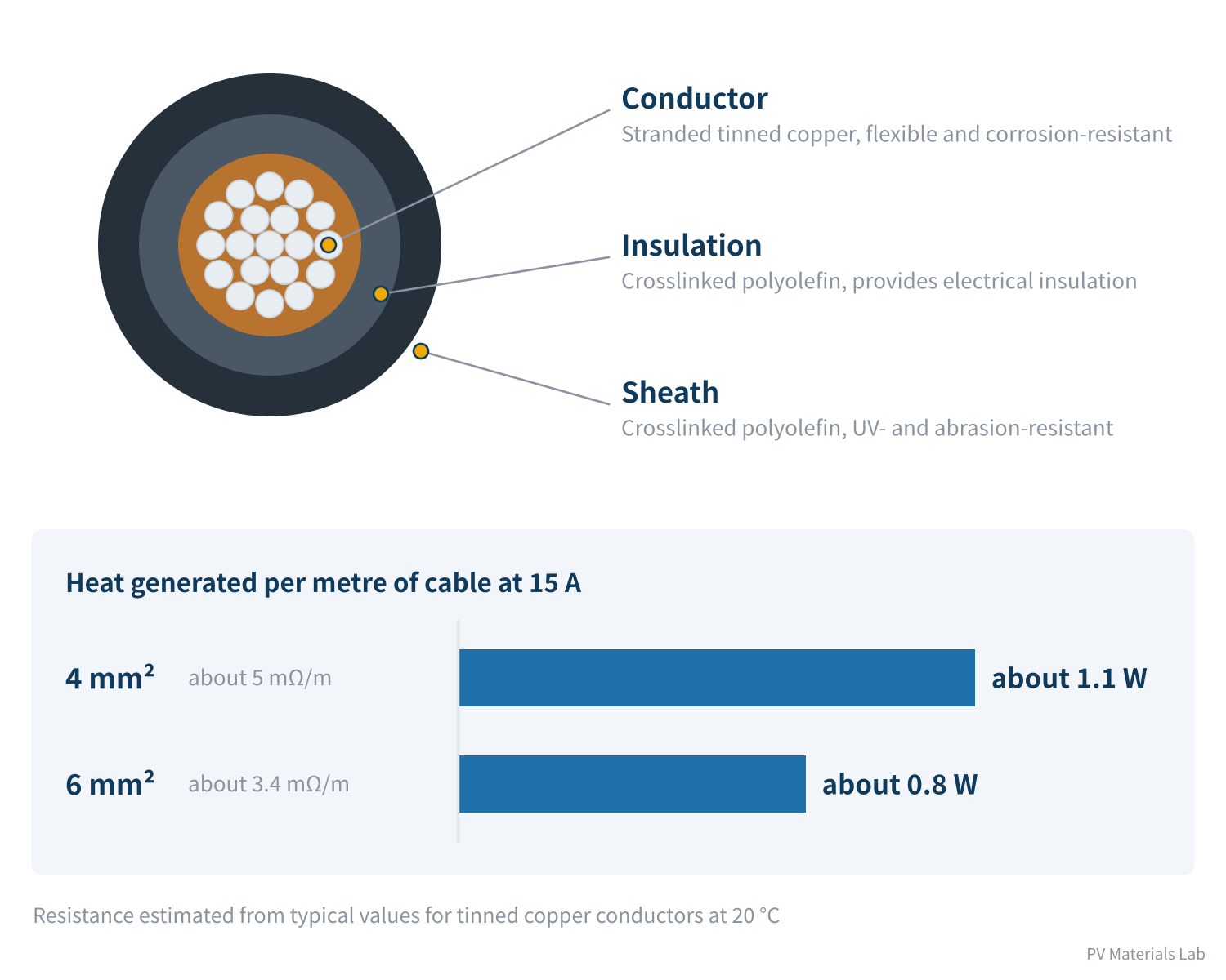
Figure 5 Structure and resistive losses of PV cable
PV cable is designed specifically for outdoor DC use: a stranded tinned-copper conductor with two layers of crosslinked polyolefin — insulation and sheath — rated at DC 1,500 V under IEC 62930 and EN 50618.
The cable heats up too
For an IEC 60228 class 5 tinned copper conductor, 4 mm² cable has a resistance of about 5.09 mΩ per metre at 20 °C. At 15 A, each metre generates about 1.1 W. Taking about 2 m in total for a module's two leads, that is over two watts of loss — already included in the module's nameplate power. In operation the cable runs hotter: copper resistance rises by about 0.4% per °C, so at 70 °C the loss is roughly another 20% higher.
That is why high-current modules are moving to 6 mm² cable: resistance falls to about 3.39 mΩ/m, cutting heat by about a third at the same current. Cable length and cross-section are real power items in module design.
Common cable failures
| Failure | Common causes | Prevention |
|---|---|---|
| Sheath cracking | Bend radius too small, long-term UV and heat ageing | Respect minimum bend radius, avoid sharp folds |
| Insulation damage | Cut by sharp frame or rack edges, or gnawed by animals | Route away from sharp edges, use conduit or cable trays |
| Falling insulation resistance | Long-term immersion in standing water | Secure cables off the ground, out of water |
| Hot ends | Poor crimping or wire size mismatched to current | Check ampacity, crimp properly |
Table 2 Common failures of PV cables
Cable failures often end up as system insulation faults — the inverter reports low insulation resistance and cannot connect to the grid, which takes time and effort to track down.
08One table: from purchasing to O&M
| Stage | Key points | Risk addressed |
|---|---|---|
| Purchasing | Lock in connectors of the same manufacturer and model plant-wide, including extension cables and device side | Cross-mating |
| Incoming | Check certificates against actual models, sample contact resistance | Counterfeits and quality variation |
| Installation | Crimp with dedicated tools, mate fully, tighten nuts to torque | Poor crimping, seal failure |
| Installation | Cap unmated connectors; secure cables, not hanging or in water | Water and sand ingress, fretting wear |
| O&M | Regular IR inspections; replace connectors with abnormal temperature promptly | Contact resistance degradation |
| O&M | Use spares of the same manufacturer and model | Cross-mating during O&M |
Table 3 Life-cycle control points for connectors and cables
Of these, IR inspection is the most effective tool in O&M: connectors with rising contact resistance appear noticeably brighter than their neighbours on a thermal camera and can be found before they burn.
09Final thoughts
1. Connectors are numerous and all in series, and DC arcs do not self-extinguish, making connectors a hot spot for fires.
2. Connectors have three critical interfaces: the crimp zone, contact zone and sealing zone.
3. Contact resistance comes from constriction and film resistance, controlled by contact pressure and plating; stress relaxation, fretting wear and oxidation accelerate its degradation.
4. Cross-mating of different brands is covered by no certification and is the most common human-made risk.
5. Field crimping must use dedicated tools; connectors are waterproof only when correctly mated.
6. Cable resistive loss is a real power item, and routing and fixing determine cable life.
This completes the four "fundamentals" articles: functions, structure and materials, bypass diodes, and connectors and cables. Next we move to "manufacturing and quality" to see how junction boxes are made.
In the next article, Junction Box Series 5 covers the production process: from injection moulding, stamping and diode soldering to assembly and inspection — how a junction box is made.
What connector or cable problems have you encountered on site? We would be glad to hear from you.
References
- IEC 62852:2014+A1:2020 Connectors for DC-application in photovoltaic systems – Safety requirements and tests
- IEC 62548:2016 Photovoltaic (PV) arrays – Design requirements (replaced by IEC 62548-1:2023 and AMD1:2025), https://www.evs.ee/en/iec-62548-1-2023
- IEC 62930 / EN 50618 Electric cables for photovoltaic systems
- IEC 60228 Conductors of insulated cables
- IEC 62790:2020 Junction boxes for photovoltaic modules – Safety requirements and tests
- pv magazine: QBE survey finds DC cabling and plug connections are most common causes of PV fires, 13 August 2026, https://www.pv-magazine.com/2026/08/13/qbe-survey-finds-dc-cabling-and-plug-connections-are-most-common-causes-of-pv-fires/
- pv magazine: Study shows consequences of PV-related fires are generally limited in severity, 31 July 2026, https://www.pv-magazine.com/2026/07/31/study-shows-consequences-of-pv-related-fires-are-generally-limited-in-severity/
- Solar Builder: Cross-mating solar PV connectors? Know that testing is not certification, https://solarbuildermag.com/featured/cross-mating-solar-pv-connectors-know-that-testing-is-not-certification/
- Bayka: Conductor resistance (IEC/EN 60228 table), https://www.bayka.de/en/service/technical-information/conductor-resistance
A PV R&D and technology team with 10+ years of experience | In-depth technical knowledge sharing
Materials · Reliability · Failure Analysis · Standards & Certification · Products · Processes
Exploring AI + PV; collaboration welcome
Disclaimer:
1. Original content reflects the authors' personal views only, is for reference only and does not constitute investment advice.
2. Reposted and cited content is credited to its source, out of respect for original work.
3. Some content was produced with AI assistance (chart generation, data retrieval, concept explanations, etc.); the core framework and key content were written by our technical team and reviewed by people.
4. If anything is inaccurate or infringes your rights, please leave a message or contact us and we will deal with it.