
Junction Box Series 6 | Bonding, Welding, Potting: The Three Module-Plant Processes That Decide Junction Box Reliability
In brief
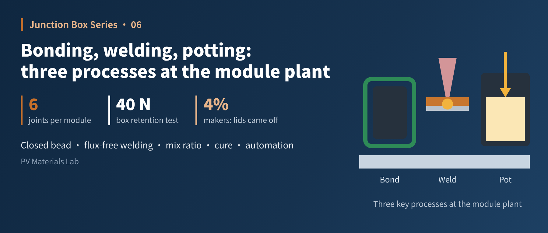
A junction box leaving its factory is only half-finished. Bonding it to the module, connecting the ribbons and filling it with potting compound — three processes done at the module plant — equally decide whether it lasts 25 years. This is the sixth article of our junction box series (manufacturing and quality: installation at the module end).
In the previous article we walked the junction box factory's production line. But a junction box that passes outgoing inspection is, strictly speaking, still only half-finished.
It is only complete once, at the module plant, it has been bonded to the module rear, connected to the ribbons and filled with potting compound. Sealing depends on the adhesive applied here, current output on the joints made here, and insulation and heat dissipation on the compound poured here — half of the three functions described in the first article are realised at the module plant.
This article is about what happens in the module plant: what each of the three key processes controls, and where each is most likely to go wrong.
01Overview: six steps, three key processes
The junction box station usually comes after lamination and framing. From leading out the ribbons to testing, it breaks down into six steps:
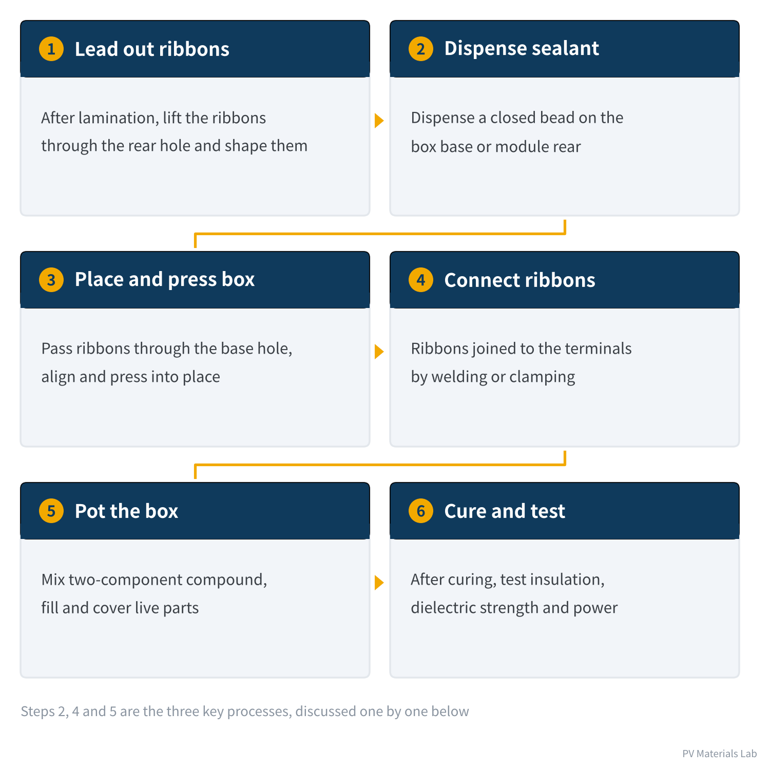
Figure 1 Six-step junction box installation at the module plant
Steps 2, 4 and 5 — bonding, connecting and potting — are the three key processes, corresponding respectively to sealing, current output, and insulation and heat dissipation. We take them one at a time.
Equipment and process routes vary between module makers — some place the box before connecting, others do everything at once in an automated all-in-one machine. This article describes common practice and focuses on the control logic of each process.
02Process 1: adhesive bonding
This bead of adhesive does two jobs at once: it holds the box firmly in place and keeps water out.
Bonding uses the one-component room-temperature-curing silicone sealant introduced in the second article. A bead is dispensed around the box base or on the module rear; when the box is pressed on, the sealant spreads to fill the gap between box base and backsheet (or rear glass).
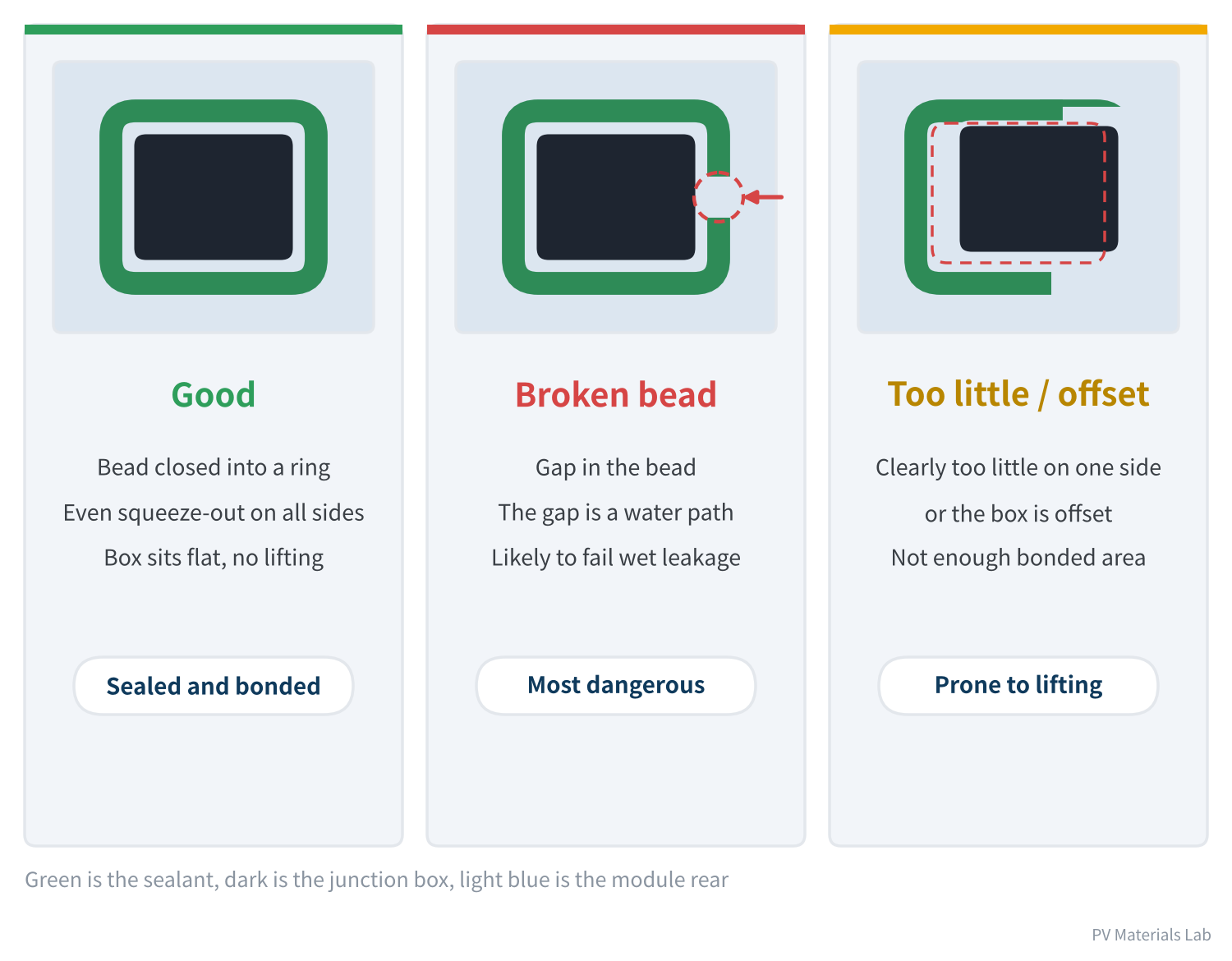
Figure 2 Three states of the sealant bead (top view)
Four control points
- Closed bead: The bead must have no break anywhere. A single gap is a direct water path into the box.
- Enough sealant: After pressing, even squeeze-out should be visible all round. Visible squeeze-out is the most direct sign that there is enough sealant.
- Timely placement: One-component sealant starts to skin over on exposure to air. The box must be placed and pressed within the specified time after dispensing, or it will not bond well.
- Clean surfaces: Dust, oil and release-agent residue on bonding surfaces weaken adhesion.
An easily overlooked risk: loading before cure
One-component sealant cures from the surface inward by absorbing moisture from the air, and full cure takes quite some time. Until then, the sealant has no strength.
If cables are pulled, or the module is flipped or stacked under load during this time, the box may shift or lift in ways hard to see, tearing a gap inside the bead. Such defects cannot be detected at the factory and only show up outdoors after a few thermal cycles.
Standards examine this bond specifically. MQT 14.1 of IEC 61215-2:2021 requires that, after humidity freeze, a 40 N force be applied at the centre of the junction box for 10 seconds in each of four directions parallel to the mounting surface and once perpendicular to it; the box must not move in a way that impairs insulation and must pass wet leakage. IEC 62790 also includes shear and retention tests after damp heat and after thermal cycling/humidity freeze. Yet in Kiwa PVEL's 2026 Scorecard, 4% of participating manufacturers still had junction box lids come off, and 9% had safety failures traced to the junction box through wet leakage testing — bonding and sealing remain very real risk points.
03Process 2: ribbon connection
The joints are where the module's internal circuit hands over to the external circuit. All the power the module generates leaves through these few points.
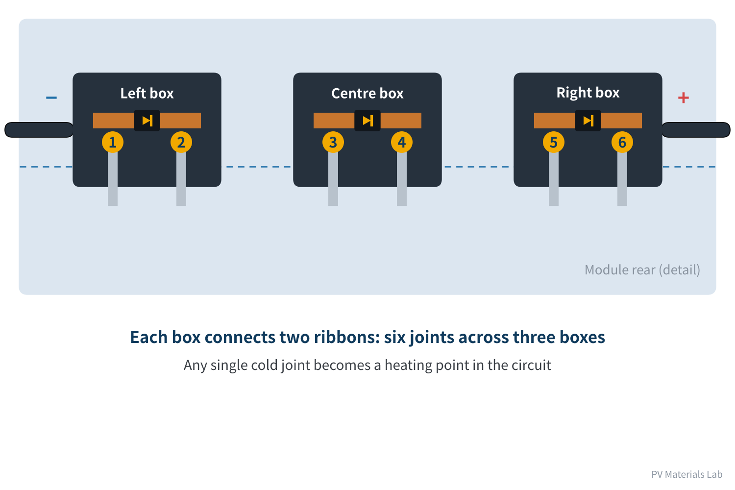
Figure 3 Three-piece junction boxes: six joints per module
With the mainstream three-piece junction box, each box connects two ribbons, so a module has six joints. All of them sit in the current path, and any one cold joint becomes the kind of "contact-resistance heating point" described in the first article.
Three joining methods
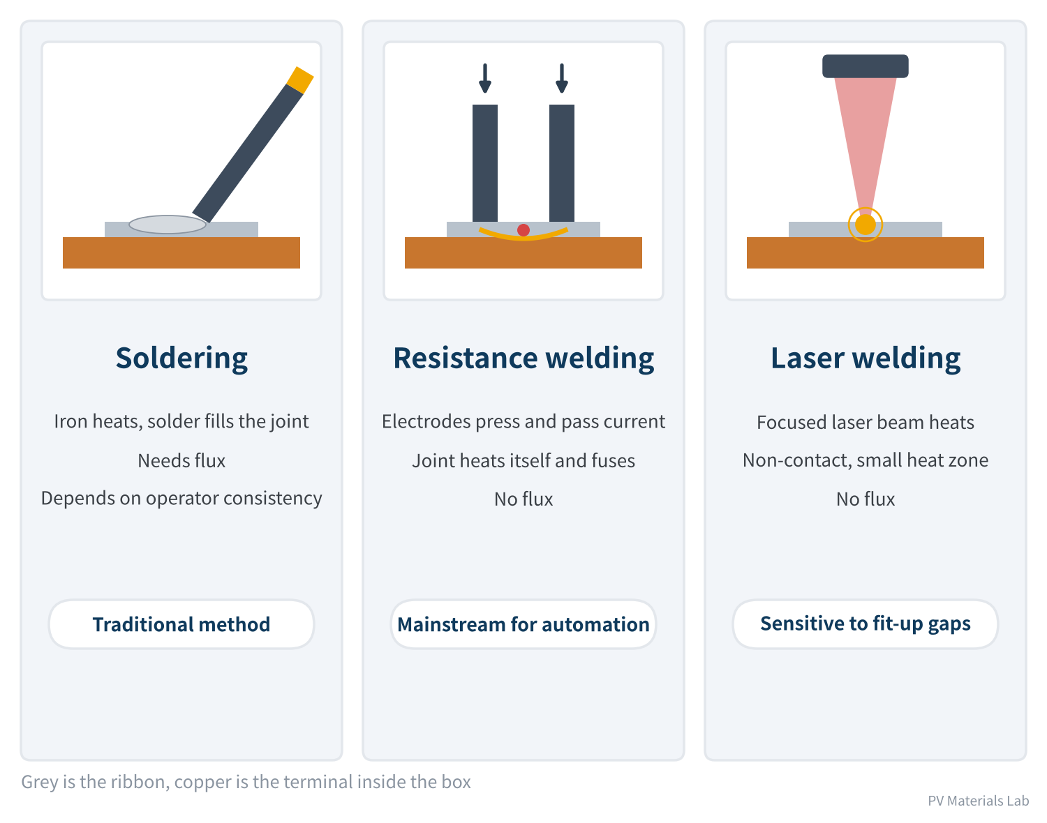
Figure 4 Three ways of joining ribbons to terminals
| Item | Soldering | Resistance / laser welding |
|---|---|---|
| Flux | Required | Not required |
| Consistency | Depends on operation, more variation | Controlled parameters, good consistency |
| Automation | Possible, but maintenance-heavy | Well suited |
| Equipment investment | Low | Higher |
| Main risks | Cold joints, flux residue | Parameter drift, electrode wear, poor fit-up |
Table 1 Soldering vs resistance/laser welding
Besides welding there is the solder-free clamping method, where a spring clip inside the box holds the ribbon. It is fast with no heat effect, but contact pressure must be maintained by the spring over the long term, placing high demands on spring material and design.
Why the industry is moving away from flux
Soldering cannot do without flux, and flux residues bring two hazards:
- Corrosion: Residues are corrosive in humid conditions and attack joints and terminals over time.
- Interfering with potting cure: As the second article explained, addition-cure potting compounds can be "poisoned" so that they do not cure, and flux residue is a common poison.
Resistance and laser welding use no flux, removing both problems at the source, and are better suited to automation — so they have become the mainstream choice for new lines.
How joints are inspected
- Visual: Is the joint in the right place, without offset, burn-through or spatter?
- Pull force: Regular sampled pull tests — destructive, but the most direct.
- Parameter monitoring: For resistance and laser welding, welding current, pressure, energy and other parameters are monitored in real time, with an alarm when out of range.
04Process 3: potting
The moment the potting compound goes in, the state inside the junction box is sealed in for good — whether good or bad.
Potting compound is two-component: parts A and B are stored separately, mixed in proportion at use, and then cure. The potting machine meters, mixes and dispenses them.
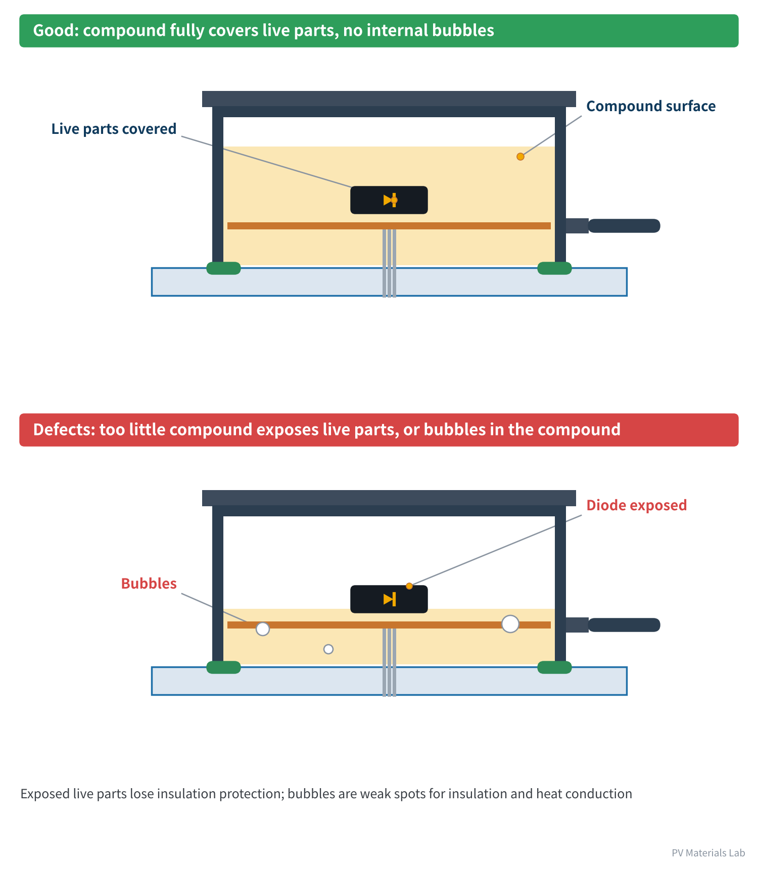
Figure 5 Good potting and two kinds of defect
Four control points
| Control point | Requirement | Consequence if lost |
|---|---|---|
| Mix ratio | Accurate A:B ratio | Incomplete cure; tacky or soft compound |
| Mixing | A and B thoroughly and evenly mixed | Local uncured spots |
| Quantity | Fully covers ribbons, joints and diode | Exposed live parts; insulation and protection fail |
| Bubbles | No significant bubbles inside | Weak spots for insulation and heat conduction |
Table 2 Four control points for potting
Ratio and mixing need the most routine checking. A common practice is to collect and weigh the output from the A and B lines separately before each shift to verify the ratio, and to keep a mixed sample to observe how it cures.
When the compound will not cure, check these first
Uncured or tacky potting is the most common abnormality in this process. Troubleshooting usually follows three directions:
- Ratio and mixing: Is the metering pump faulty? Is the mixing tube blocked or due for replacement?
- Environment: Condensation-cure compounds need moisture to cure and slow down markedly in cold, dry winter conditions.
- "Poisoning": If tackiness appears only at interfaces, suspect flux residue or incompatibility with other materials first.
05Curing: the underestimated "waiting"
Both sealant and potting compound need time to cure. This waiting looks like doing nothing, yet it is the step most easily squeezed in the whole flow.
The reason is practical: cure time directly sets line takt time and the floor space of the curing area. The slower the cure, the more work in progress and the tighter the space. During capacity ramp-up, the temptation to "wait a bit less" is strong.
But moving on before adequate cure causes two kinds of problems:
- Distorted tests: Testing insulation, dielectric strength or wet leakage before cure either produces false failures or masks real defects.
- Physical damage: Uncured modules that are flipped, stacked or packed let the compound flow and deform, and boxes shift under load.
So curing conditions — time, temperature and humidity — should be specified and recorded as process parameters, not judged by feel as "about done". Switching to fast-curing compounds or adding a heated curing section is the right way to raise takt time.
06Automation: why it is the trend
Early junction box installation was largely manual: hand dispensing, hand placement and soldering irons. Mainstream lines now use automated junction box installation equipment that integrates vision positioning, dispensing, box placement, welding, potting and inspection.
Automation is driven by more than labour cost:
- Three-piece boxes make manual work harder: One box per module became three, with six joints; manual takt time and consistency cannot keep up.
- New welding methods need equipment: Resistance and laser welding are processes born for automation.
- Traceable process data: Sealant quantity, welding parameters and inspection images are recorded for every module, so problems can be traced to a specific station and time.
Automation also brings new management priorities: regular calibration of equipment parameters, replacement intervals for consumables such as electrodes and mixing tubes, and the false-call rate of vision inspection all belong in routine checks.
07Common defects and where to look
| Defect | Check first | Process |
|---|---|---|
| Junction box lifting or detaching | Sealant quantity, cleanliness of bonding surface, loading before cure | Bonding |
| Wet leakage failure | Breaks in the bead, box offset, adequate potting | Bonding, potting |
| Local heating in the box | Cold joints, drifting welding parameters | Welding |
| Tacky, uncured potting | Ratio, mixing, ambient temperature and humidity, material compatibility | Potting |
| Bubbles or dents in the potting surface | Dispensing speed, quantity setting, air entrained during mixing | Potting |
Table 3 Common defects at the module end and where to look
Use this table like the process matrix in the previous article: first locate the process from the symptom, then go back through that process's control points one by one.
08Final thoughts
1. Half of a junction box's three functions are realised at the module plant through bonding, welding and potting.
2. The core of bonding is a closed bead and enough sealant, with no loading before cure.
3. Three-piece junction boxes have six joints per module; resistance and laser welding have become mainstream because they need no flux and suit automation.
4. Potting must control ratio, mixing, quantity and bubbles; when it will not cure, check these and material compatibility first.
5. Curing conditions are process parameters and must not be squeezed by feel.
6. Automation delivers not just efficiency but consistency and traceability.
This completes the whole journey of the junction box from raw materials to being fitted on a module. Whether it was made well must ultimately be shown by testing.
In the next article, Junction Box Series 7 covers test methods and procedures: what type testing examines, and how incoming inspection and process monitoring should be done.
Which process gives you the most trouble when installing junction boxes at the module end? We would be glad to hear from you.
References
- IEC 62790:2020 Junction boxes for photovoltaic modules – Safety requirements and tests
- IEC 61215-2:2021 Terrestrial photovoltaic (PV) modules – Design qualification and type approval – Part 2: Test procedures
- IEC 61730-2 Photovoltaic (PV) module safety qualification – Part 2: Requirements for testing
- Sinovoltaics: IEC 61215 MQT 14: Robustness of Terminations Test for Solar Modules, https://sinovoltaics.com/learning-center/testing/iec-61215-mqt-14-robustness-of-terminations-test-for-solar-modules/
- TÜV Rheinland: Junction box – Overview of check routine, https://www.tuv.com/content-media-files/master-content/services/products/0206-tuv-rheinland-photovoltaic-components/tuv-rheinland-check-routine-junction-box-for-pv-systems-en.pdf
- Kiwa PVEL: 2026 PV Module Reliability Scorecard – Failures, https://2026scorecardsbx.pvel.com/failure
A PV R&D and technology team with 10+ years of experience | In-depth technical knowledge sharing
Materials · Reliability · Failure Analysis · Standards & Certification · Products · Processes
Exploring AI + PV; collaboration welcome
Disclaimer:
1. Original content reflects the authors' personal views only, is for reference only and does not constitute investment advice.
2. Reposted and cited content is credited to its source, out of respect for original work.
3. Some content was produced with AI assistance (chart generation, data retrieval, concept explanations, etc.); the core framework and key content were written by our technical team and reviewed by people.
4. If anything is inaccurate or infringes your rights, please leave a message or contact us and we will deal with it.