
Junction Box Series 5 | From Resin Pellets to Finished Product: How Is a Junction Box Made?
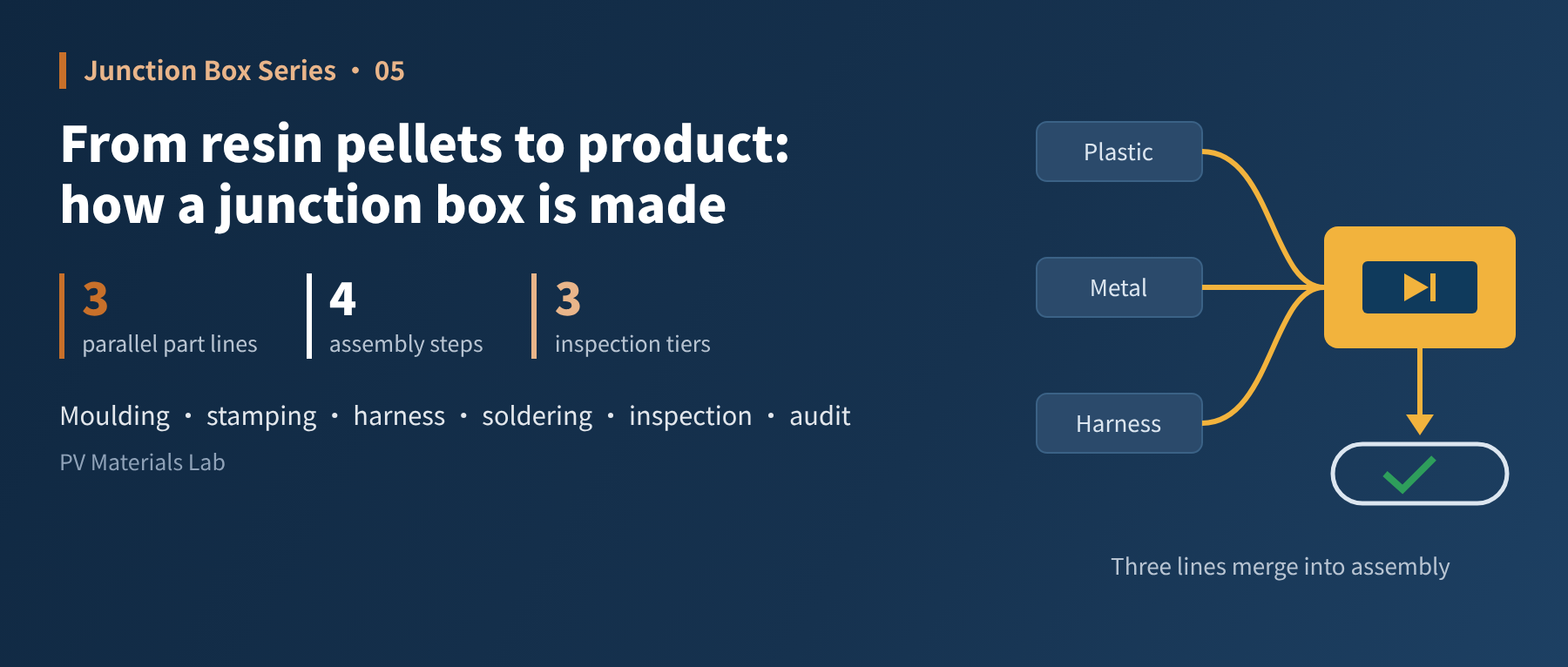
In brief
Injection moulding, stamping, diode soldering, cable crimping, assembly and inspection — a walk along a junction box production line to see what each process controls. This is the fifth article of our junction box series and the first of its "manufacturing and quality" part.
The first four articles formed the "fundamentals" part, covering what a junction box is and why it is designed the way it is. From this article we move to "manufacturing and quality": how it is made and how it is inspected.
However good the design, every box has to be made one by one on a production line. With the same drawings and the same materials, products from different factories can differ widely in reliability — and the difference lies in process control. Third-party testing bears this out: Kiwa PVEL's 2026 Reliability Scorecard shows that 21% of participating module manufacturers had a junction-box-related failure, including 9% with a safety failure traced to the junction box through wet leakage testing — sometimes found at initial characterisation, before any stress test — and 4% whose junction box covers came off.
In this article we walk into a junction box factory and follow the line: what does each process do, and where is it most likely to go wrong?
01Overview: three lines in parallel, merging at assembly
Junction box production is not a single straight line but three parallel component lines that merge on the assembly line:
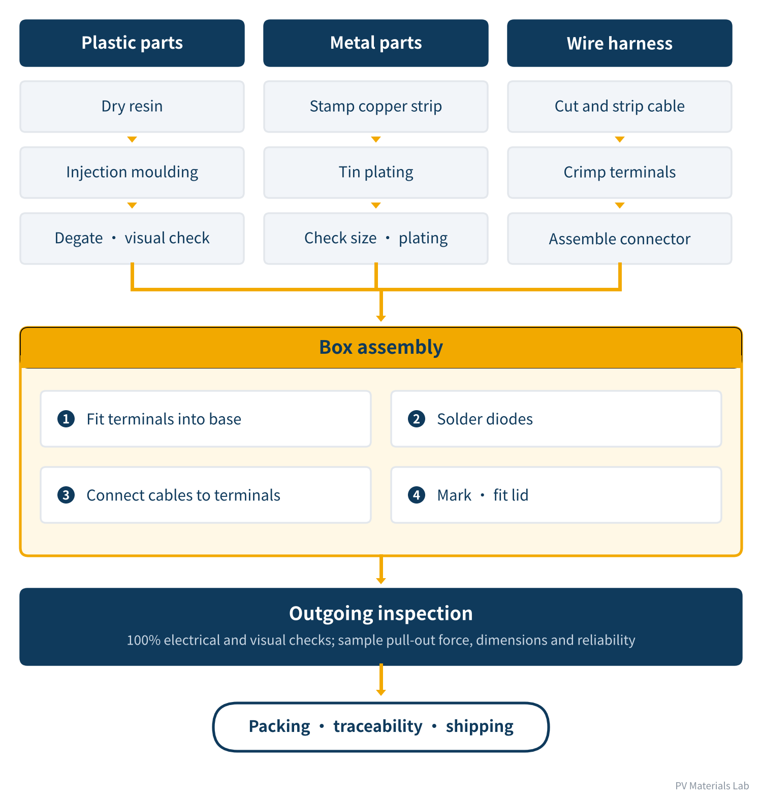
Figure 1 Overall production flow: three lines in parallel, merging at assembly
- Plastic parts line: Turns resin pellets into bases, lids and connector housings.
- Metal parts line: Turns copper strip into conductive terminals and connector contacts.
- Wire harness line: Assembles cables and connectors into leads with plugs.
The outputs of the three lines, plus purchased bypass diodes, come together on the assembly line and are inspected, packed and shipped.
This article covers the processes inside the junction box factory. Bonding the box to the module, soldering the ribbons and potting and curing are done at the module factory and are covered in the next article. Process routes also vary between companies; this article describes common practice.
02Plastic parts: injection moulding
Injection moulding determines the box's "body": whether it is strong enough, dimensionally accurate, and reliably flame-retardant.
The process
- Drying the resin: Before feeding, pellets must be dried at the temperature and time recommended by the material supplier. Wet resin degrades at high temperature, directly affecting part performance.
- Injection moulding: The pellets are melted and injected into the mould, held under pressure, cooled and ejected.
- Degating and checking: Gates are removed and appearance and key dimensions are checked.
What most often goes wrong
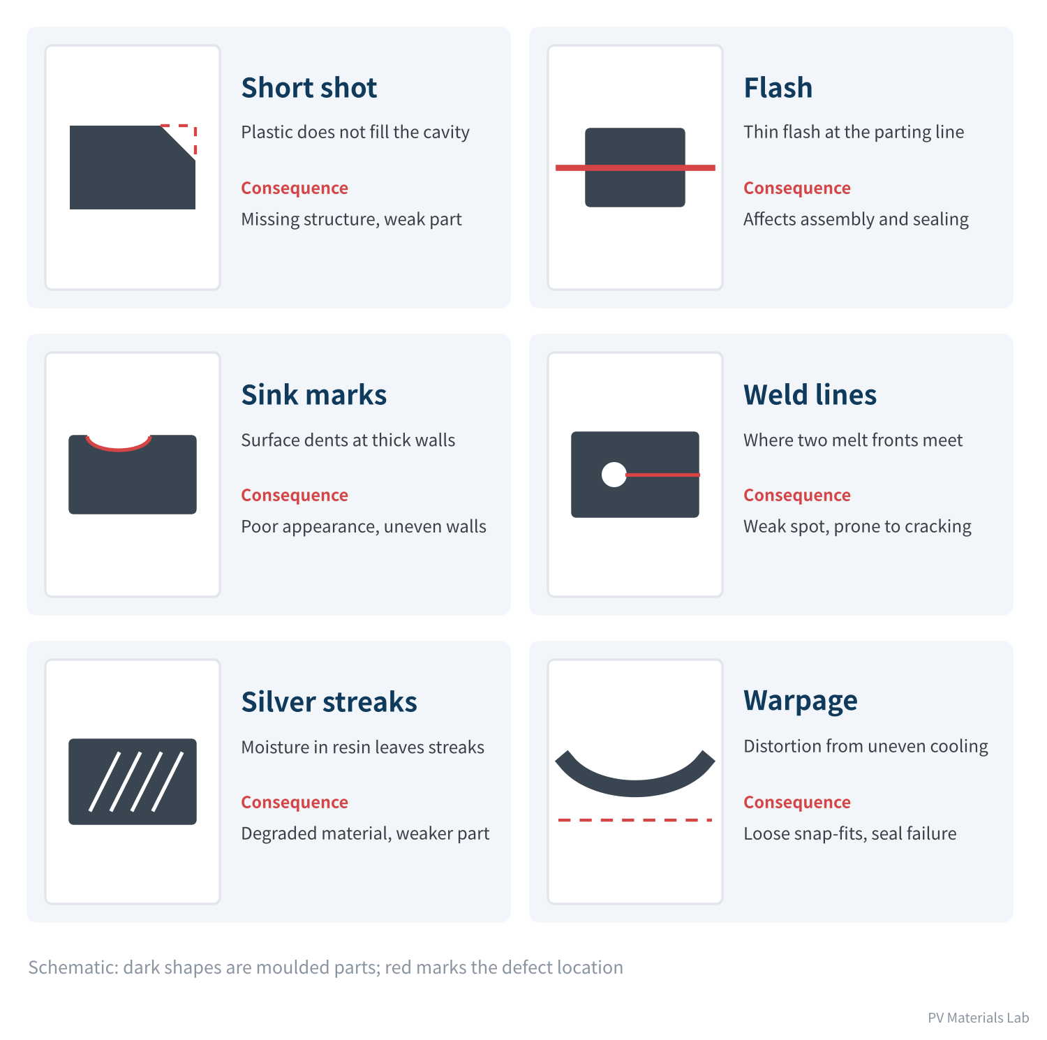
Figure 2 Six common defects in moulded parts
Of these six defects, weld lines and warpage do the most direct harm to junction boxes: the former are weak spots where cracks readily start after thermal cycling; the latter stop the lid's snap-fits from closing tightly, so sealing fails outright — and many cases of "lids coming off" mentioned above are related to this.
An easily overlooked control point: regrind
Moulding produces runners and rejects, which can be ground up and mixed back into virgin resin as "regrind". This is a normal cost-saving measure, but each pass through high-temperature processing degrades the material a little.
Too much regrind compromises flame retardancy and mechanical strength — precisely the properties examined most closely in certification. In the UL system, how much regrind a material grade may contain without affecting its recognition is stated on that grade's UL Yellow Card, and it varies widely between grades. So the regrind ratio must have a clear upper limit, consistent with the material certification, and be strictly enforced — a must-check item in any factory audit.
03Metal parts: stamping and plating
The metal parts determine the "road" for the current: how wide it is, how smooth it is, and whether it will corrode.
- Stamping: Coiled copper strip is fed into a press and formed step by step into terminals by blanking and bending in progressive dies.
- Plating: Terminals are tin-plated to prevent copper oxidation and ensure reliable soldering later. Some connector contacts are silver-plated.
- Inspection: Dimensions, flatness and burrs are checked, along with plating thickness and adhesion.
Three points of attention for stamped parts:
| Point | Why it matters | Consequence of defects |
|---|---|---|
| Burrs | Sharp burrs can pierce insulation and scratch cables | Insufficient insulation distance, risk of breakdown |
| Flatness | Diodes and terminals must sit flat to solder well | More solder voids, poorer heat dissipation |
| Plating | Plating that is too thin or poorly adhered cannot protect the copper | Lower solderability and higher contact resistance after oxidation |
Table 1 Three points of attention for stamped parts
As the second article explained, terminals are both conductors and heat sinks. Once the copper grade and thickness are set, they must not be swapped casually in production — this is where "cost reduction" is most tempting and needs the closest watch.
04Wire harness: cutting, crimping and connector assembly
The harness line turns coiled cable into leads fitted with connectors:
- Cutting and stripping: Cable is cut to the specified length and insulation stripped at both ends to expose the copper.
- Terminal crimping: The connector's metal terminal is crimped onto one end of the cable.
- Connector assembly: The crimped cable is inserted into the connector housing, the seal fitted and the rear nut tightened.
Crimping principles and quality criteria were covered in detail in the previous article. Factory crimping is done by automated equipment with far better consistency than manual field work, but it still relies on crimp height monitoring and pull-out force sampling.
Cable length is also a controlled item. As calculated in the previous article, each extra metre of 4 mm² cable at 15 A adds about a watt of loss; too short, and modules cannot be connected. So the lead length for each layout is agreed with the module maker.
05Box assembly: four steps into one
Step 1: fitting terminals into the base
The conductive terminals are fixed into the plastic base. Common methods are snap-fitting and heat staking; terminals can also be insert-moulded into the base. Whatever the method, terminals must not be loose, or the solder joints will be under long-term stress.
Step 2: diode soldering
This is the process on the whole line with the highest technical content and the greatest impact on reliability. SMD and module-packaged diodes are usually soldered to the copper terminals.
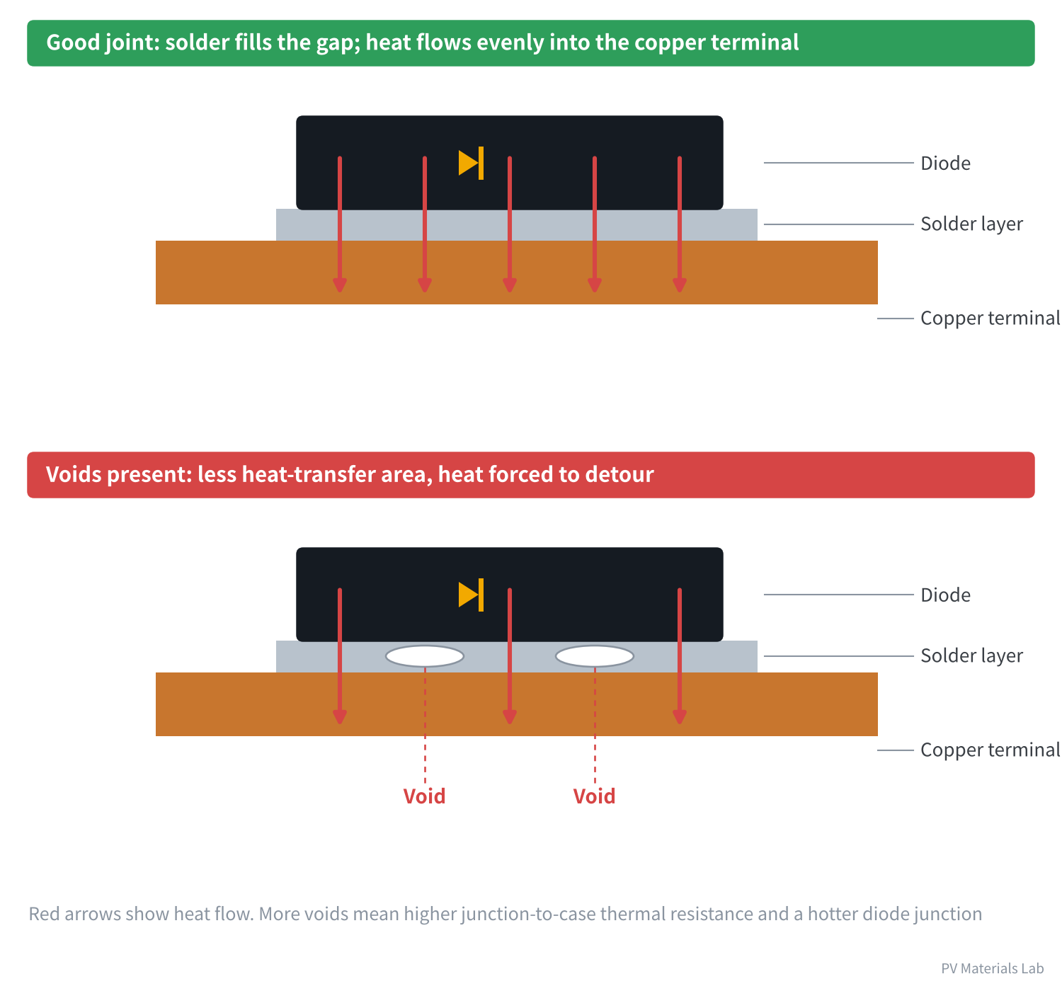
Figure 3 Diode soldering: why voids matter
As the third article explained, diode heat is carried away mainly by the copper terminals. The solder layer is the "bridge" between diode and terminal. Voids in it reduce the heat-transfer area, raising junction-to-case thermal resistance and, with it, the diode junction temperature.
This process has four control points:
- Solder voids: Invisible to the eye; monitored by X-ray sampling.
- Soldering temperature: Excessive temperature or time can thermally damage the diode chip.
- Polarity error-proofing: A reversed diode defeats bypass protection entirely; error-proofing design and 100% checks are essential.
- ESD protection: Schottky diodes are ESD-sensitive; workstations, tools and people must all be ESD-protected.
Step 3: connecting cables to terminals
The other end of the harness is connected to the terminals inside the box, commonly by crimping or resistance welding, and a locking structure then secures and seals the cable at the box's cable outlet. This step affects both current output and outlet sealing.
Step 4: marking and fitting the lid
The base is marked with the model, ratings, polarity, certification marks and a batch traceability code, and the lid is fitted. The traceability code may look trivial, but it is the only clue for tracing a problem back to a specific batch and specific raw materials later.
06Outgoing inspection: three tiers
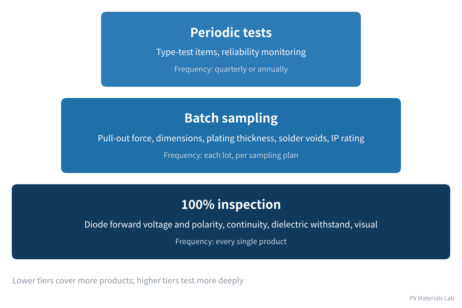
Figure 4 Three tiers of outgoing inspection
- 100% inspection: Every product must pass. Mainly electrical tests that can be done quickly in-line — diode forward voltage and polarity, circuit continuity, dielectric withstand — plus visual inspection.
- Batch sampling: Samples drawn from each lot per a sampling plan, mainly for destructive or time-consuming items such as pull-out force, dimensions, plating thickness, solder voids and ingress protection.
- Periodic tests: Products are regularly sent for key type-test items and reliability monitoring to confirm that production units remain consistent with the certified samples.
The three tiers complement each other: 100% inspection ensures "every unit is assembled correctly", sampling ensures "this lot's process has not drifted", and periodic tests ensure "design and materials have not changed over time".
A diode's forward voltage is a very sensitive "health indicator": abnormally low forward voltage may mean the chip has suffered ESD or thermal damage and its leakage has increased; abnormally high forward voltage may indicate a poor solder joint. One test screens out reversed, missing and some damaged devices at once.
07Mapping processes to functions
The first article described the three functions of a junction box. Now we can answer: which process safeguards each function?
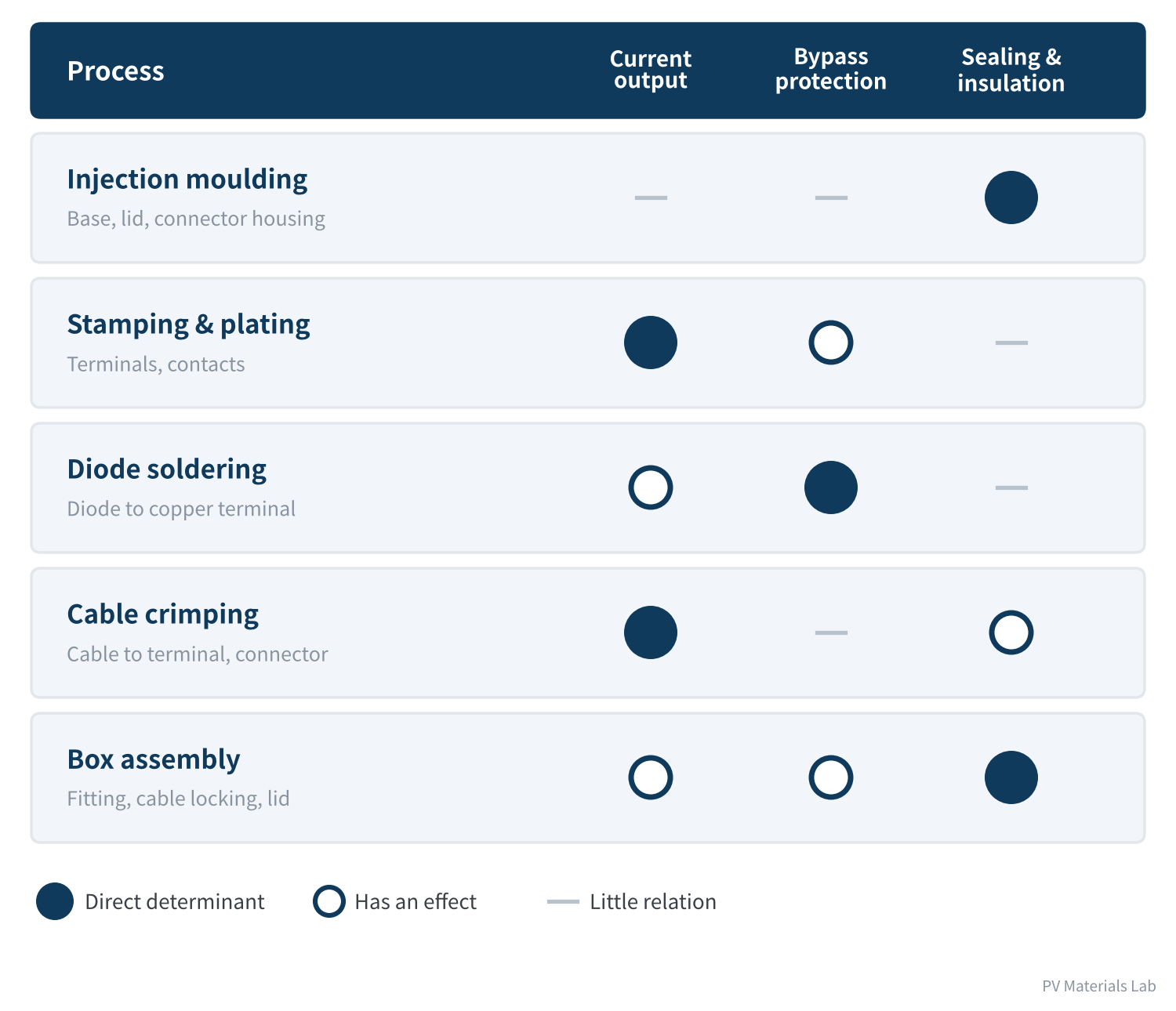
Figure 5 Which process affects which function
The chart can also be read backwards: when a product has a problem with one function, follow the solid dots to the corresponding processes. High contact resistance — check stamping/plating and crimping first; an overheating diode — check soldering first; water ingress — check moulded part dimensions and assembly first.
08What to look at when auditing a junction box factory
From the perspective of a module maker or buyer walking into a junction box factory, these six items are most worth the time:
- Drying and regrind: Are there drying records? Does the regrind ratio have an upper limit, how is it controlled, and is it consistent with what the material certification allows?
- Diode management: How are incoming diodes inspected, and is ESD protection in storage and at workstations adequate?
- Soldering monitoring: Is there X-ray inspection capability? What are the void criteria and sampling frequency?
- 100% test coverage: Which items does in-line testing cover, how are rejects quarantined, and how is test equipment checked?
- Change management: When material grades, diode models or suppliers change, is the product revalidated, and does it match the critical components list filed with the certification?
- Traceability: Given a finished-goods batch number, can the plastic, copper and diode batches used be traced?
The fifth item is where problems most often arise. A certificate covers a specific combination of materials and structure; if materials are quietly swapped, the certificate no longer means what it says. IEC TS 62915 (retest requirements after changes to certified modules), covered in Article 11 of our encapsulant series, applies equally to changes in key components such as junction boxes.
09Final thoughts
1. Junction box production runs three component lines in parallel that merge at assembly, followed by inspection and shipping.
2. Injection moulding determines strength, dimensions and flame retardancy; the regrind ratio is a key control point.
3. Stamping and plating lay the foundation for conduction and heat dissipation; watch burrs, flatness and plating.
4. Diode soldering is the most technical process; solder voids directly affect junction temperature.
5. Outgoing inspection has three tiers — 100% inspection, batch sampling and periodic tests — each covering a different risk.
6. Factory audits should focus on regrind, diode management, soldering monitoring, test coverage, change management and traceability.
Once the junction box leaves the factory, only half the story has been told. It still has to be bonded to the module rear, have ribbons soldered and be filled with potting compound — processes that happen at the module factory and equally determine its final reliability.
In the next article, Junction Box Series 6 covers installation at the module end: adhesive bonding, ribbon soldering and potting cure — three key processes in the module factory.
Which items matter most to you when auditing a junction box factory? We would be glad to hear from you.
References
- IEC 62790:2020 Junction boxes for photovoltaic modules – Safety requirements and tests
- IEC 62852 Connectors for DC-application in photovoltaic systems – Safety requirements and tests
- UL 94 Standard for Tests for Flammability of Plastic Materials
- IEC TS 62915:2023 Photovoltaic (PV) modules – Type approval, design and safety qualification – Retesting
- Kiwa PVEL: 2026 PV Module Reliability Scorecard – Failures, https://2026scorecardsbx.pvel.com/failure
- RTP Company: Yellow Cards Notes (UL Yellow Card notes on regrind), https://rtpcompany.com/fusion_element/yellow-cards-notes
A PV R&D and technology team with 10+ years of experience | In-depth technical knowledge sharing
Materials · Reliability · Failure Analysis · Standards & Certification · Products · Processes
Exploring AI + PV; collaboration welcome
Disclaimer:
1. Original content reflects the authors' personal views only, is for reference only and does not constitute investment advice.
2. Reposted and cited content is credited to its source, out of respect for original work.
3. Some content was produced with AI assistance (chart generation, data retrieval, concept explanations, etc.); the core framework and key content were written by our technical team and reviewed by people.
4. If anything is inaccurate or infringes your rights, please leave a message or contact us and we will deal with it.