
Junction Box Series 9 | The Junction Box Is Already Certified — Why Does Module Certification Test It Again?
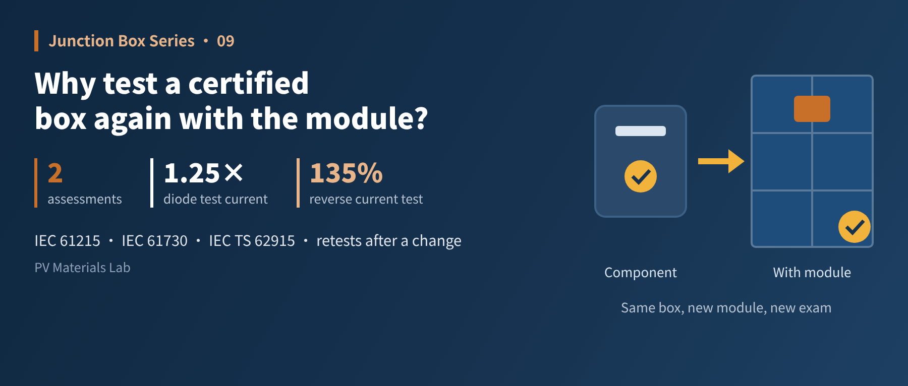
In brief
Component certification tests the box itself; module certification tests the box and module together. How the two assessments differ, and what has to be retested when the junction box changes. This is the ninth article in our junction box series (Standards and Reliability: the junction box in module certification).
The last article covered the junction box's own certification. But anyone who has taken a module through certification knows that the story does not end when a certified junction box arrives at the module factory. When the module goes for certification, the junction box is tested all over again together with it.
Worse, if a module maker wants to switch to a different junction box supplier after mass production starts, the module certification cannot simply carry over, even if the new supplier's box is also certified.
This article explains why the box is tested twice, what the second test covers, and what changing the junction box means.
01Two assessments, two different questions
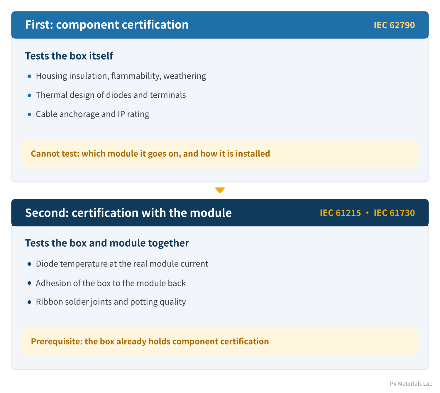
Figure 1 Two assessments, two different questions
Component certification follows IEC 62790 and tests the box itself: is the housing insulation sufficient, is the material flame-retardant, is the thermal design of diodes and terminals sound, is the cable anchored firmly?
But some things it cannot test. As we explained in article 6, half of a junction box's three main functions are realised in the module factory: sealing depends on the adhesive the module maker applies, current extraction depends on the solder joints the module maker makes, and heat dissipation depends on the module the box is mounted on. None of this exists yet at component certification.
Certification with the module tests exactly this part: whether the box and module, once combined, are reliable and safe as a whole.
IEC 61730, the module safety standard, sets requirements for the components a module uses: junction boxes, cables and connectors must comply with their respective component standards. In other words, a certified junction box is a prerequisite for module certification, not a substitute for it.
02IEC 61215: performance and reliability
IEC 61215 (currently the 2021 second edition) assesses whether a module design can withstand long-term outdoor use. Five groups of tests relate directly to the junction box:
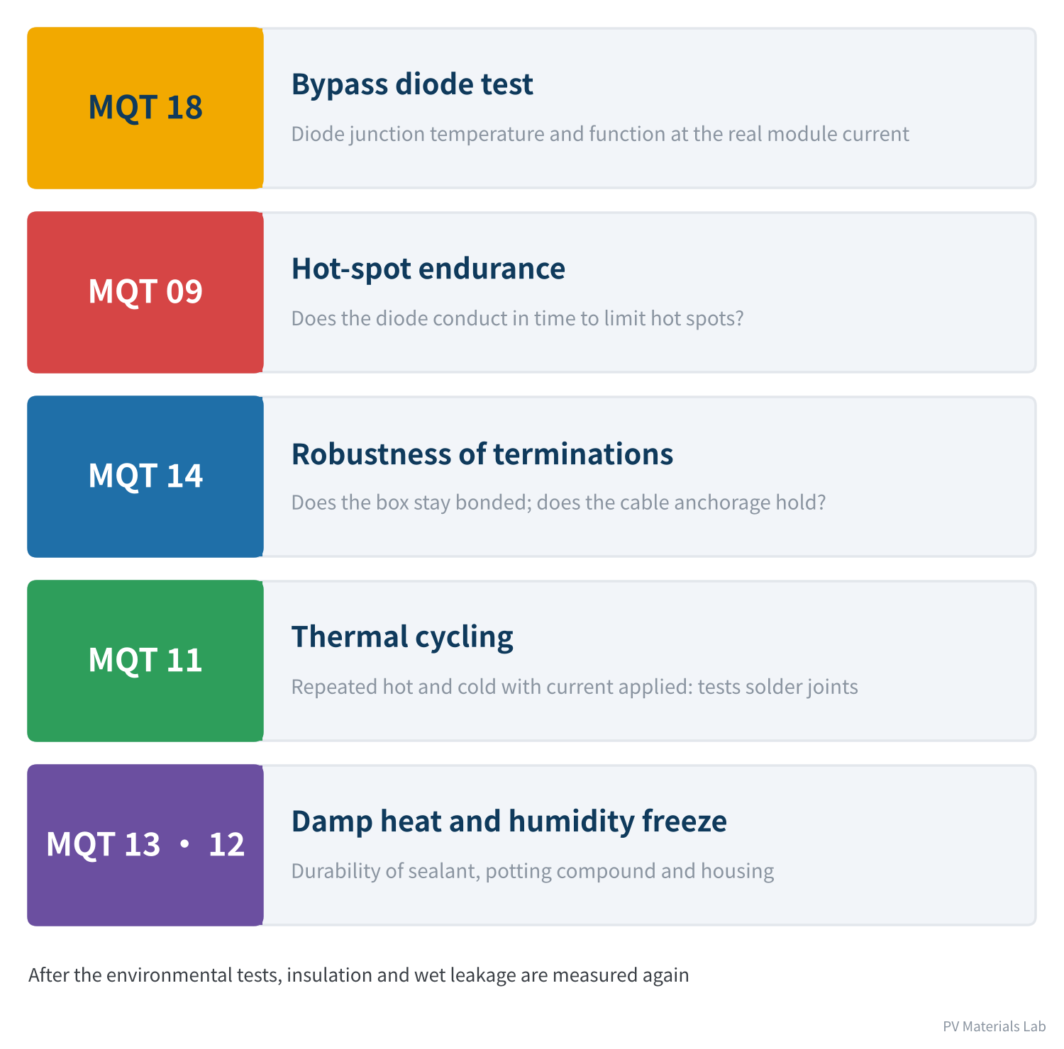
Figure 2 Tests in IEC 61215 directly related to the junction box
Bypass diode test (MQT 18)
We covered its principle and procedure in articles 3 and 7. One point bears repeating: the diodes were thermally tested during component certification too, but then the current was the box's own declared rated current and the cooling conditions were the mounting method defined by the standard.
In module certification, the current becomes this module's actual short-circuit current, and the cooling conditions become this module's actual construction: the module is heated to 75 °C, Isc is applied for 1 hour, then the current is raised to 1.25 × Isc for another hour. The same box can give a completely different result.
Hot-spot endurance test (MQT 09)
The hot-spot test is aimed at the cells, but it also tests the diode indirectly: when cells are shaded, the diode must conduct in time to bypass that cell string, which is what limits hot-spot temperature. A sluggish or failed diode lets the hot spot run away.
Robustness of terminations (MQT 14)
It has two parts. One applies force to the junction box (MQT 14.1: 40 N, held 10 s in each direction) to check that the box stays bonded to the mounting surface. The other is the cord anchorage test (MQT 14.2).
The first part is really testing the adhesive interface rather than the box: does this sealant, on this backsheet or glass, hold this box? It is performed after UV preconditioning, 50 thermal cycles and 10 humidity-freeze cycles, so it tests adhesion after ageing.
In the 2021 edition, the second part is done on the junction box separately according to IEC 62790, and results from component certification can be used; junction boxes with integrated connectors are exempt.
Thermal cycling (MQT 11)
The module is cycled repeatedly between −40 °C and 85 °C, with current applied (the maximum-power current) whenever the module is above 25 °C. Different materials expand at different rates, so each hot-cold swing tugs at the solder joints between the ribbons and the terminals. The current is there so that defective joints heat up, degrade further and reveal themselves.
For the junction box, thermal cycling mainly tests those six solder joints.
Damp heat and humidity freeze (MQT 13, MQT 12)
High temperature and humidity test the durability of the sealant, potting compound and housing material. The test itself does not give a verdict; what matters is the insulation and wet leakage measurements afterwards. Only then do you find out whether moisture has found a way in.
03IEC 61730: safety
IEC 61215 asks "can it work properly for a long time?"; IEC 61730 (currently the 2023 third edition) asks "could it cause electric shock, fire or injury?". Its tests are numbered MST, and these relate to the junction box:
| No. | Test | Relevance to the junction box |
|---|---|---|
| MST 25 | Bypass diode thermal test | Is the diode temperature safe when conducting? |
| MST 07 | Bypass diode functionality test | Does the diode still work after the other tests? |
| MST 26 | Reverse current overload test | Do the box and solder joints overheat and ignite under back-fed current? |
| MST 42 | Robustness of terminations test | Box retention and cable anchorage |
| MST 14 | Impulse voltage test | Are clearances between live parts sufficient? |
| MST 16, 17 | Insulation test, wet leakage current test | Insulation in dry and wet conditions |
| MST 35, 36 | Peel test, lap shear strength test | Reliability of adhesive joints |
Table 1 Safety tests in IEC 61730 related to the junction box
Worth a closer look: reverse current overload
This is one of the most characteristic tests in IEC 61730, and one of the most overlooked.
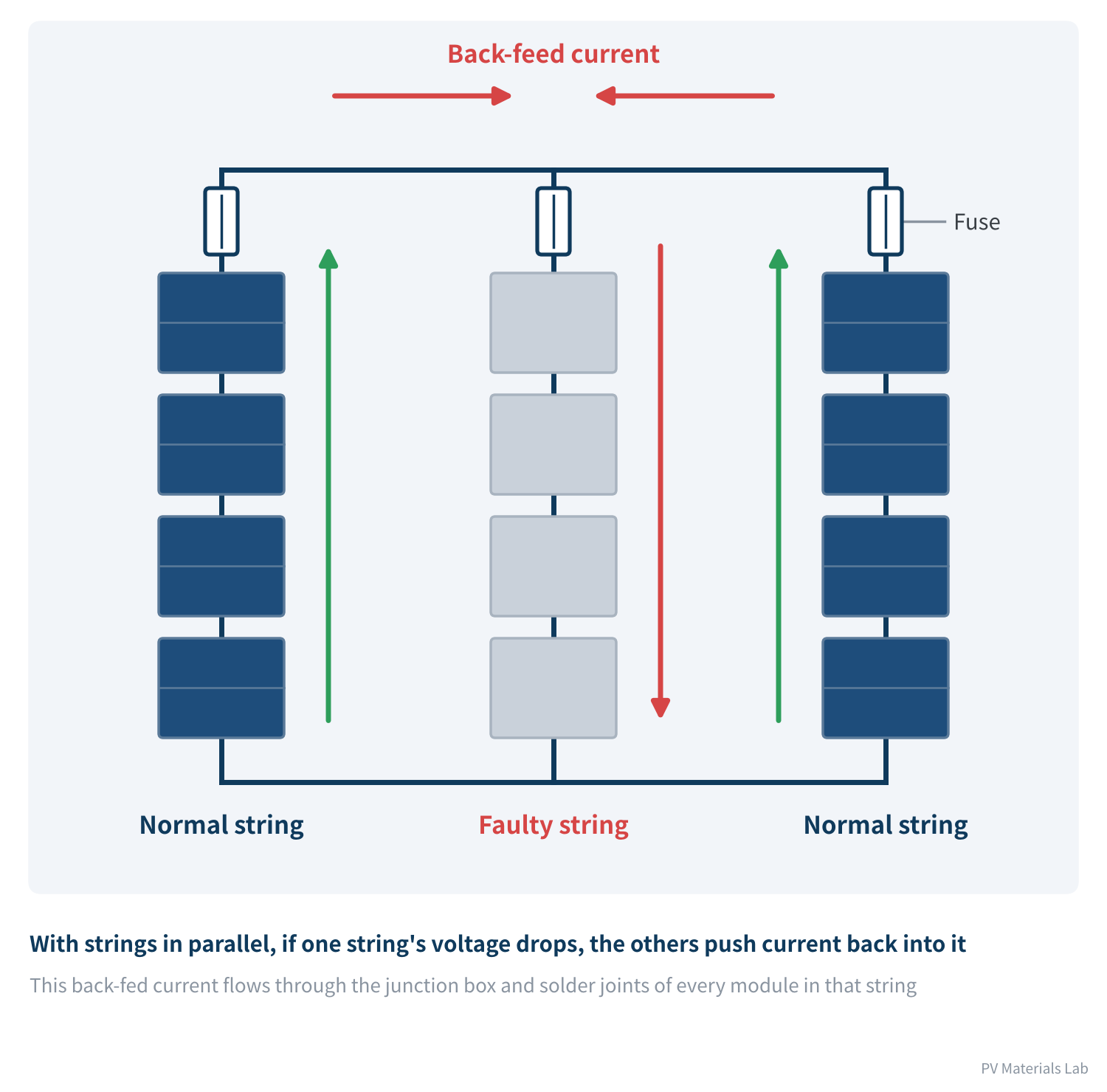
Figure 3 Where reverse current comes from
In a power plant, several strings are connected in parallel. If one string's voltage drops because of a fault, shading or a wiring mistake, current from the other strings is pushed back into it, flowing through every module in that string in the opposite direction to normal generation.
This back-fed current can be much larger than the module's normal operating current, and it flows through exactly the junction box terminals, solder joints and ribbons of each module. The test applies a reverse current of 135% of the module's overcurrent protection rating for 2 hours and checks whether anything gets hot enough to ignite.
The "maximum series fuse rating" on the module nameplate is what this test verifies. It tells system designers how large a series fuse can be: if it is too large, the back-fed current is not cut off in time and the module may burn first.
04Why the same box gives different results on a different module
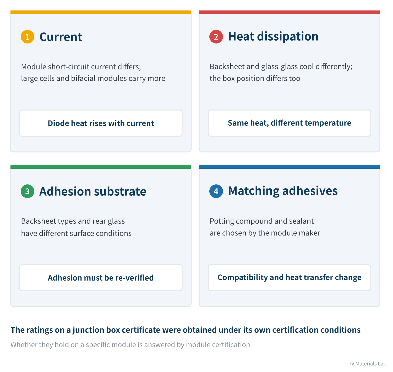
Figure 4 Same junction box, different module, new exam
- The current changes: larger cells and bifacial modules keep pushing short-circuit current up. Diode heating rises with current, so a box that passes on a low-current module may overheat on a high-current one.
- The cooling changes: backsheet and glass-glass modules have different rear materials and therefore different heat transfer and dissipation. The same heat produces a different diode temperature.
- The adhesion substrate changes: different backsheets and rear glasses have very different surface conditions, so the same adhesive's bond strength must be verified again.
- The matching adhesives change: the potting compound and sealant are chosen by the module maker. Their thermal conductivity and compatibility with the housing both affect the final result.
A junction box has a rated current of 25 A in its component certification. It is used on a bifacial module with a front-side short-circuit current of 18 A and a bifaciality of 70%.
Under IEC 61215:2021, the diode thermal test for bifacial modules uses the short-circuit current at bifacial stress irradiance (BSI: 1000 W/m² front, 300 W/m² rear):
18 × (1 + 0.3 × 0.70) ≈ 21.8 A
In the second hour the current is raised by a further 1.25×: 21.8 × 1.25 ≈ 27.2 A
Looking only at the front, 18 × 1.25 = 22.5 A, and a 25 A box seems to have plenty of headroom. With the rear-side gain included, the test current already exceeds its rating. Add the less favourable cooling of a glass-glass build, and only the test will tell whether it passes.
So the rating on a junction box certificate cannot be taken as "the value I can use on my module". Between the two lies a module certification.
05What must be retested when the junction box changes
Once a module is certified, the certificate covers a specific bill of materials: this cell, this backsheet, this junction box, this adhesive. Any change to any of them must be assessed for retesting.
The basis for that assessment is IEC TS 62915 (currently the 2023 second edition), a technical specification dedicated to which tests must be repeated after a module change. It sets out the retest combinations for each type of change.
In terms of mechanism, junction box-related changes broadly affect four categories of tests:
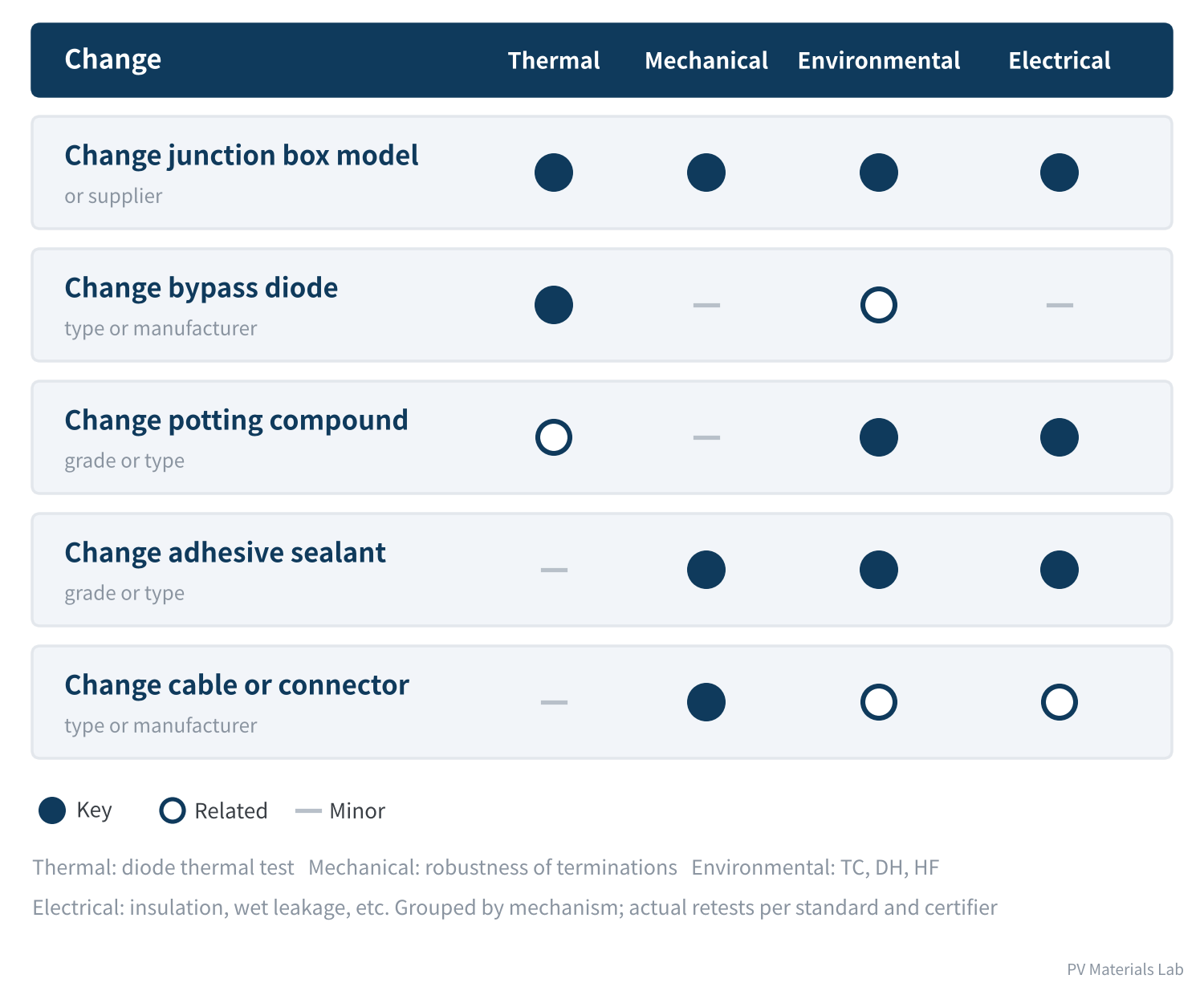
Figure 5 Which test categories junction box-related changes affect
- Changing the junction box model or supplier: the change with the widest impact; thermal, mechanical, environmental and electrical safety nearly all need re-verification.
- Changing only the diode: the focus is the thermal test.
- Changing the potting compound or sealant: the focus is insulation and wet leakage after environmental ageing; for the sealant, adhesion strength as well.
- Changing the cable or connector: the focus is cable anchorage, and the new component must itself hold the corresponding component certification.
Figure 5 groups changes by mechanism to help explain why certain tests must be repeated. The actual list of retests follows the current edition of IEC TS 62915 and the certification body's decision; do not use the figure itself as the basis.
The real cost
Retesting costs time and money. A round of retests that includes thermal cycling and damp heat takes months. This directly shapes a module maker's supply chain strategy:
- Plan multiple suppliers early: if you want two junction box suppliers backing each other up, test both in during product certification rather than bringing one in hastily when supply runs short.
- Combinations multiply fast: two junction box suppliers, two potting compounds, two sealants and three backsheets give, in theory, their product: 2 × 2 × 2 × 3 = 24 combinations. Every combination actually used should be covered by certification.
- Bundle changes: combining several changes into one round of retests is much more economical than testing them one by one.
Beyond certification, third-party reliability testing confirms these risks. In Kiwa PVEL's 2026 PV Module Reliability Scorecard, 17% of participating manufacturers had at least one bypass diode failure and 21% had junction box-related failures, and modules entering that programme have usually already obtained IEC certification.
06Five recommendations for module makers
- Size for the highest current: check diode margin against the highest-current module variant, and for bifacial modules include rear-side gain under BSI conditions.
- Qualify as a system: verify and lock the junction box, potting compound and sealant as one package rather than evaluating them separately.
- Pre-test first: run screening tests before certification, focusing on the diode thermal test and wet leakage after ageing, the two most likely to fail.
- Schedule early: build second-supplier qualification into the certification plan, with enough time for retests.
- Check regularly: periodically confirm that the bill of materials on file for the module certification matches the materials actually in use.
07Final thoughts
Certification answers "is the design qualified?". But qualification is only the starting point. What a junction box actually endures over more than twenty years outdoors, and how it gradually fails, is the subject of the next article.
1. The junction box is tested twice: component certification tests the box itself; module certification tests the box and module together.
2. Component certification is a prerequisite for module certification, not a substitute.
3. In IEC 61215, the key junction box-related tests are the diode thermal test, hot spot, robustness of terminations, thermal cycling and damp heat.
4. IEC 61730 tests again from a safety standpoint; reverse current overload is the typical example.
5. Put the same box on a different module and the current, cooling, adhesion substrate and adhesives all change, so results do not carry over; for bifacial modules, the test current includes rear-side gain.
6. Changing the junction box requires a retest assessment under IEC TS 62915, and a multi-supplier strategy must be planned in advance.
In the next article, Junction Box Series 10 looks at the junction box's key role in module reliability: under thermal cycling, damp heat, humidity freeze and hot spots, what the junction box goes through.
What retesting pitfalls have you run into when switching junction box suppliers? We would be glad to hear from you.
References
- IEC 61215-1:2021, IEC 61215-2:2021 Terrestrial photovoltaic (PV) modules – Design qualification and type approval
- IEC 61730-1:2023, IEC 61730-2:2023 Photovoltaic (PV) module safety qualification
- IEC TS 62915:2023 Photovoltaic (PV) modules – Type approval, design and safety qualification – Retesting
- IEC 62790:2020 Junction boxes for photovoltaic modules – Safety requirements and tests
- IEC 62979:2017 Photovoltaic modules – Bypass diode – Thermal runaway test
- Intertek: UL 61215-2 Standards Update Notice (MQT 18.1 BSI current, MQT 14 clauses), https://www.intertek.com/siteassets/resources/sun/2024/ul-61215-2-sun-rev-7-28-2021-ed-4-1-2025-amendment-1.pdf
- BIS: IS/IEC 61730-2 Test Report Form, https://www.bis.gov.in/wp-content/uploads/2026/01/2026.01.05_IS-IEC-61730-2_v2.0_F.pdf
- Sinovoltaics: IEC 61215 MQT 18: Bypass Diode Testing, https://sinovoltaics.com/learning-center/testing/iec-61215-mqt-18-bypass-diode-testing-for-solar-modules/
- Sinovoltaics: IEC 61215 MQT 14: Robustness of Terminations, https://sinovoltaics.com/learning-center/testing/iec-61215-mqt-14-robustness-of-terminations-test-for-solar-modules/
- LONGi: Analysis of junction box selection for modules based on 182mm wafers, https://www.longi.com/en/news/6738/
- Kiwa PVEL: 2026 PV Module Reliability Scorecard – Failures, https://2026scorecardsbx.pvel.com/failure
A PV R&D and technology team with 10+ years of experience | In-depth technical knowledge sharing
Materials · Reliability · Failure Analysis · Standards & Certification · Products · Processes
Exploring AI + PV; collaboration welcome
Disclaimer:
1. Original content reflects the authors' personal views only, is for reference only and does not constitute investment advice.
2. Reposted and cited content is credited to its source, out of respect for original work.
3. Some content was produced with AI assistance (chart generation, data retrieval, concept explanations, etc.); the core framework and key content were written by our technical team and reviewed by people.
4. If anything is inaccurate or infringes your rights, please leave a message or contact us and we will deal with it.