
Junction Box Series 7 | What Tests Must a Junction Box Pass? Type Testing, Incoming Inspection and Process Monitoring Explained
In brief
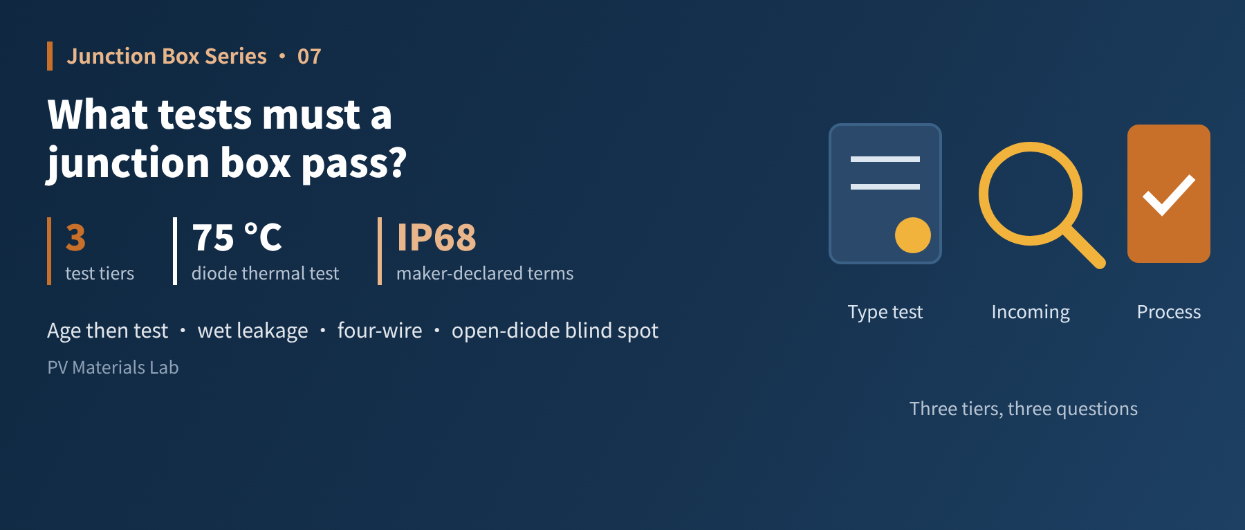
Type testing answers "is the design good enough?", incoming inspection answers "is this batch right?", and process monitoring answers "is it installed well?" — three tiers of testing, each covering a different risk. This is the seventh article of our junction box series (manufacturing and quality: test methods and procedures).
The previous two articles covered how junction boxes are made and installed. Whether they are made well and installed firmly must ultimately be shown by testing.
But "testing" is too broad a word. Months of type testing in a certification lab and a few minutes of sampling by a module maker's incoming inspector are both called testing, yet they answer completely different questions.
This article splits junction box testing into three tiers: what each tier tests, how it tests, and how to read the results.
01Three tiers, three questions
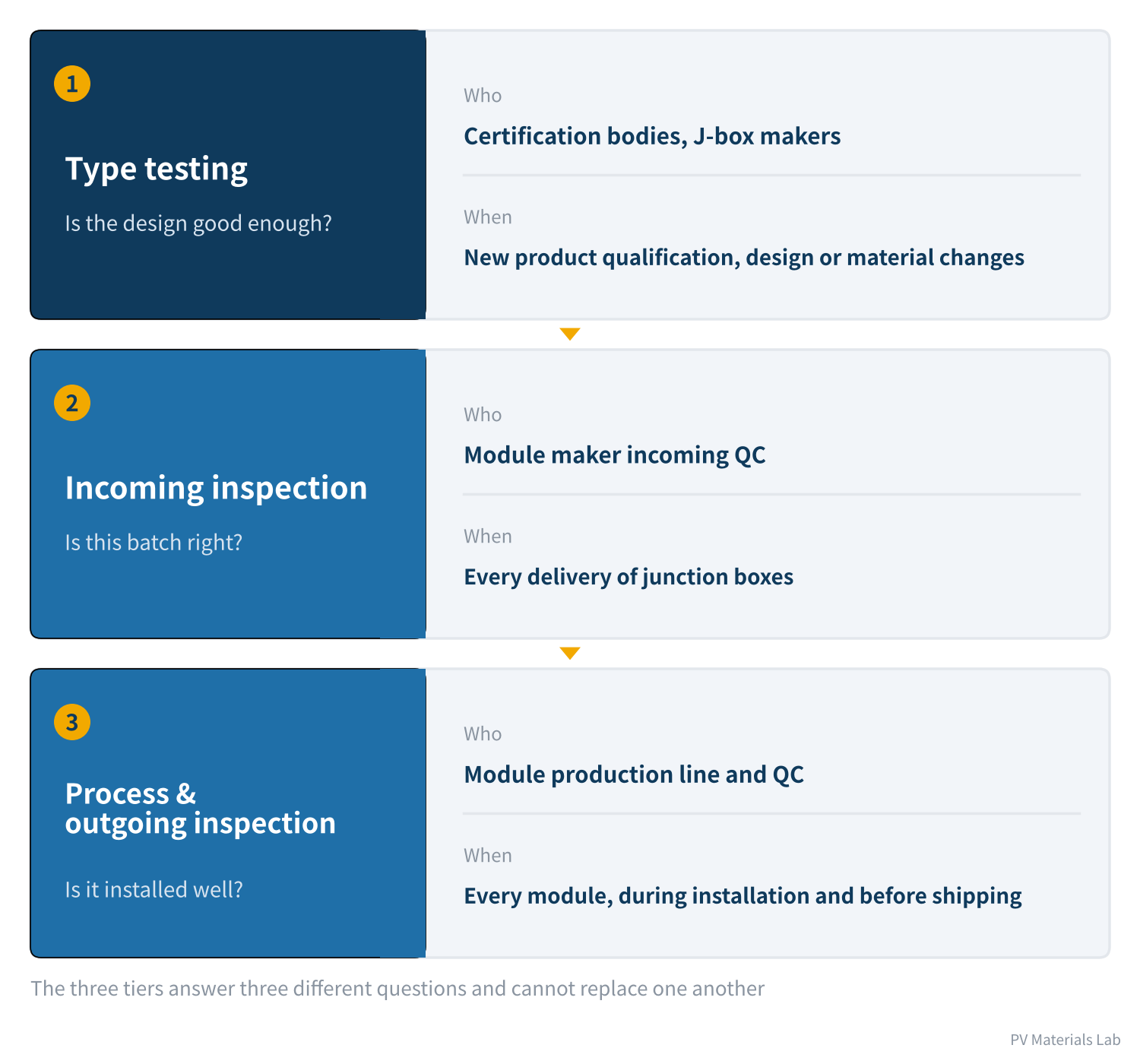
Figure 1 Three tiers of junction box testing
- Type testing: Answers "is this design good enough?". It examines design and materials with few samples, a full set of tests and a long duration, leading to certification.
- Incoming inspection: Answers "is this batch right?". It confirms that the delivered product is the same thing that was certified and agreed, and that this batch has no manufacturing defects.
- Process and outgoing inspection: Answers "is it installed well?". It confirms that the junction box has been correctly installed on every module.
The three tiers cannot replace one another. Passing type testing does not mean every production batch is good; passing incoming inspection does not mean all is well once the box is on the module.
02Type testing: what it examines
Junction box type testing follows IEC 62790 (currently the second edition of 2020). The standard contains many items, which can be grouped by purpose into five categories:
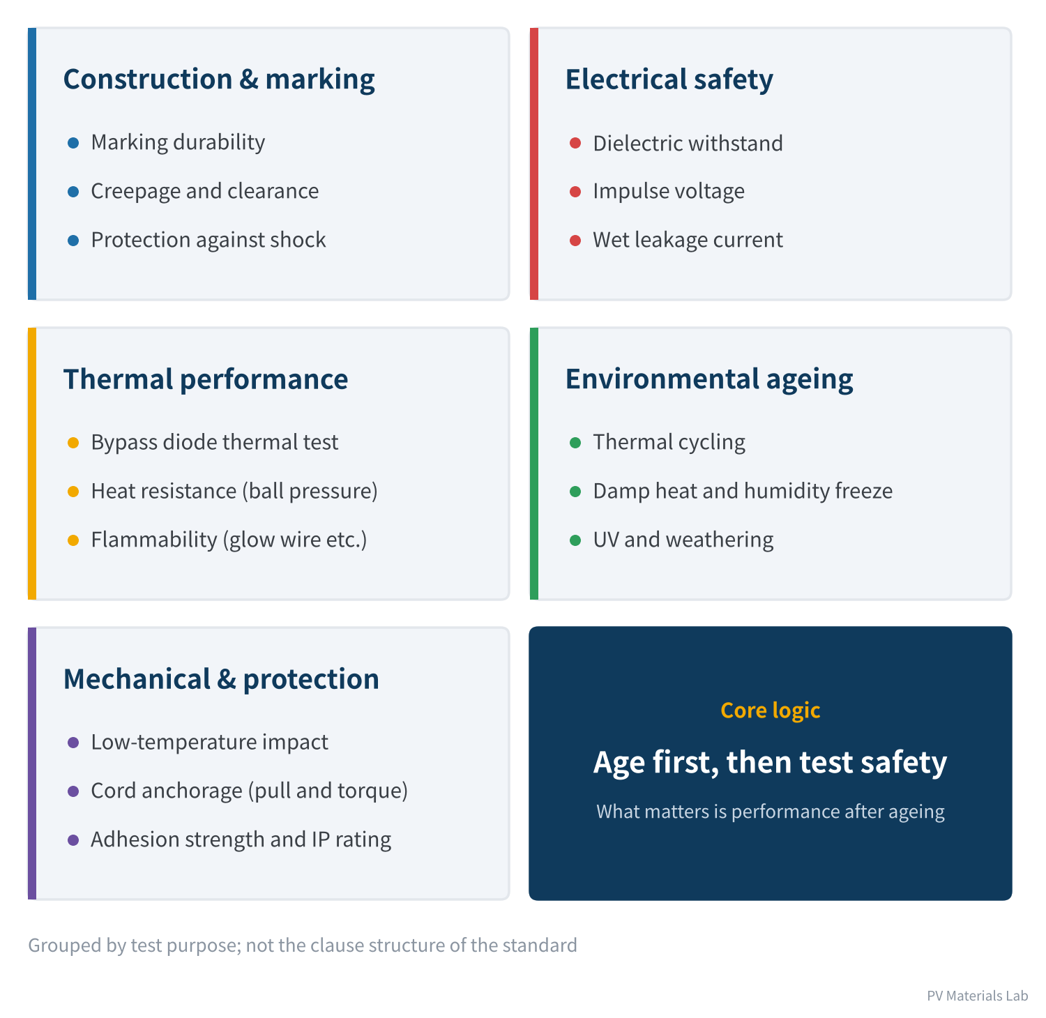
Figure 2 Five categories of type test
| Category | Question answered | Function (from Article 1) |
|---|---|---|
| Construction & marking | Are distances between live parts, and from live parts to outer surfaces, sufficient? | Sealing & insulation |
| Electrical safety | Will it break down at high voltage or leak when wet? | Sealing & insulation |
| Thermal performance | Is diode temperature under control when conducting; is the plastic heat- and flame-resistant? | Bypass protection |
| Environmental ageing | Do materials degrade after thermal cycling, damp heat and UV? | All three |
| Mechanical & protection | Can the cable be pulled out, does the box stay bonded, is it waterproof? | Current output, sealing & insulation |
Table 1 Five categories of type test and the functions they cover
Core logic: age first, then test safety
The most important design idea in type testing is chaining individual tests into sequences:
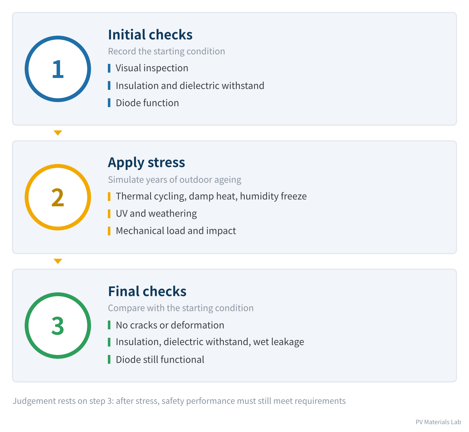
Figure 3 Test sequences: stress is the means, final checks are the goal
Environmental tests such as thermal cycling and damp heat do not by themselves give a pass or fail. The real judgement comes after the stress, when visual inspection, insulation, dielectric withstand, wet leakage and diode function are checked again to see whether safety performance still meets the requirements. In TÜV Rheinland's public junction box check routine, for example, one sequence applies 200 thermal cycles from −40 °C to +85 °C at rated current, measuring contact resistance before and after, with the final value not exceeding 150% of the initial value; another applies 1,000 hours of damp heat at 85 °C/85% RH, followed by shear, retention, dielectric withstand and wet leakage tests.
Passing a dielectric test with a new box is easy; passing it after ageing is hard. That is why, when reading a test report, you should look at the sequence rather than isolated individual tests.
03Four tests worth a closer look
① Bypass diode thermal test
The principle was covered in Article 3; here are the steps in IEC 62790:
- Fit a thermocouple: A thermocouple is attached to the diode case to measure case temperature.
- Heat and stabilise: The sample is heated and stabilised at 75 °C.
- Rated current: A forward current equal to the module short-circuit current is applied for 1 hour, and the case temperature recorded.
- Derive junction temperature: Junction temperature is calculated from case temperature, dissipated power and junction-to-case thermal resistance, and must not exceed the device's rated limit.
- Overload current: The current is raised to 1.25 times and held for another hour.
- Confirm function: After the test, the diode must still work normally.
The step most prone to error is the first: thermocouple position and attachment directly affect the case temperature reading. If it is misplaced, the calculated junction temperature cannot be trusted. Note that at module level, MQT 18.1 of IEC 61215-2:2021 now derives junction temperature by forward-voltage calibration rather than thermocouple attachment, so results from the two methods should not be compared directly.
② Wet leakage current test
It checks whether the insulation between live parts and the outside remains reliable under wet conditions. Taking MQT 15 of IEC 61215 at module level as an example:
- Solution: A water solution with resistivity of no more than 3,500 Ω·cm at 22 ± 2 °C; the sample is immersed, and the junction box and cable entries are thoroughly sprayed.
- Voltage: A DC voltage of 500 V or the maximum system voltage, whichever is greater, is applied between live parts and the solution for 2 minutes.
- Criteria: Insulation resistance is measured; samples smaller than 0.1 m² need at least 400 MΩ, while modules need insulation resistance times area of at least 40 MΩ·m².
Wet leakage is the most "sensitive" test in the whole sequence. A break in the sealant bead, an uncovered spot in the potting, a hairline crack in the housing — undetectable when dry, they are exposed as soon as the sample is wet. That is why it always comes after the ageing tests.
③ Cord anchorage test
A specified pull and torque are applied to the cable, and the displacement of the cable relative to the box and any damage to internal connections are checked. It simulates pulling during installation and years of wind sway, verifying that the cable-locking structure keeps external forces away from solder joints and crimps.
④ Ingress protection test
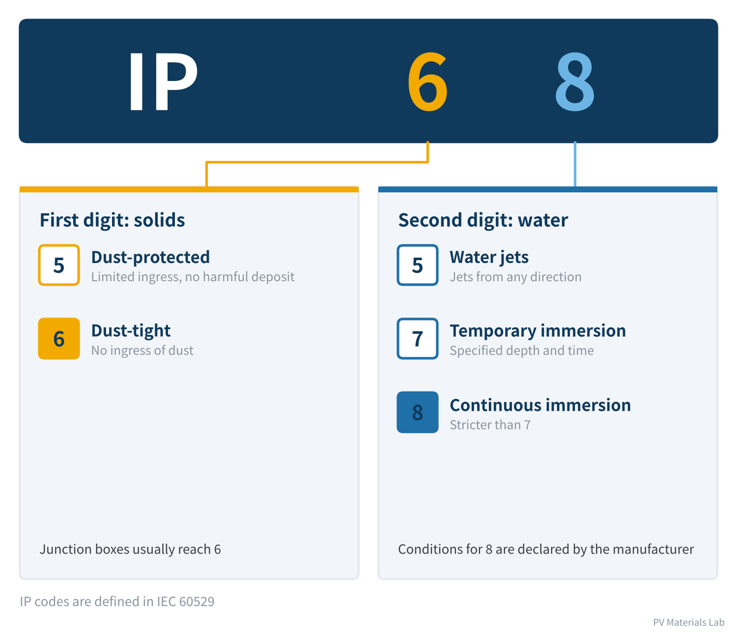
Figure 4 Reading an IP code: the two digits after "IP"
The degree of protection is written as "IP + two digits": the first is protection against solid objects, the second against water. IEC 62790 requires at least IP55 for junction boxes, while boxes and connectors on the market are commonly rated IP67 or IP68.
Under IEC 60529, the immersion depth and time behind the "8" in IP68 are declared by the manufacturer (or agreed between supplier and user); the standard only requires them to be more severe than IP67. So two products both rated IP68 may differ in actual water resistance. When comparing, look at the conditions the manufacturer declares.
04Incoming inspection: what module makers do
Type testing is done once; incoming inspection is done for every batch. Within limited time and cost, it has to catch the most likely problems.
| Item | Method | Problems targeted |
|---|---|---|
| Appearance and dimensions | Visual, gauges | Transport damage, wrong model or version |
| Marking and certification consistency | Check certificate and critical components list | Mixed parts, unapproved material changes |
| Diode forward voltage and polarity | Voltage drop at constant current | Reversed, missing or damaged devices |
| Circuit resistance | Four-wire micro-ohmmeter | Poor crimps and joints |
| Cable length and cross-section | Gauges | Out of specification |
| Pull-out force | Tensile tester | Weak cable anchorage and crimps |
| Connector mating and intermateability | Mating-force gauge, mating with reference parts | Dimensional deviation |
| Adhesive compatibility | Small-sample cure test | No cure after a batch or supplier change |
Table 2 Incoming inspection items for junction boxes
Why circuit resistance needs the four-wire method
Junction box circuit resistance is in the milliohm range, while the two probes of an ordinary multimeter can themselves have a few tenths of an ohm of lead and contact resistance. Measured that way, the reading is mostly the probes' own resistance.
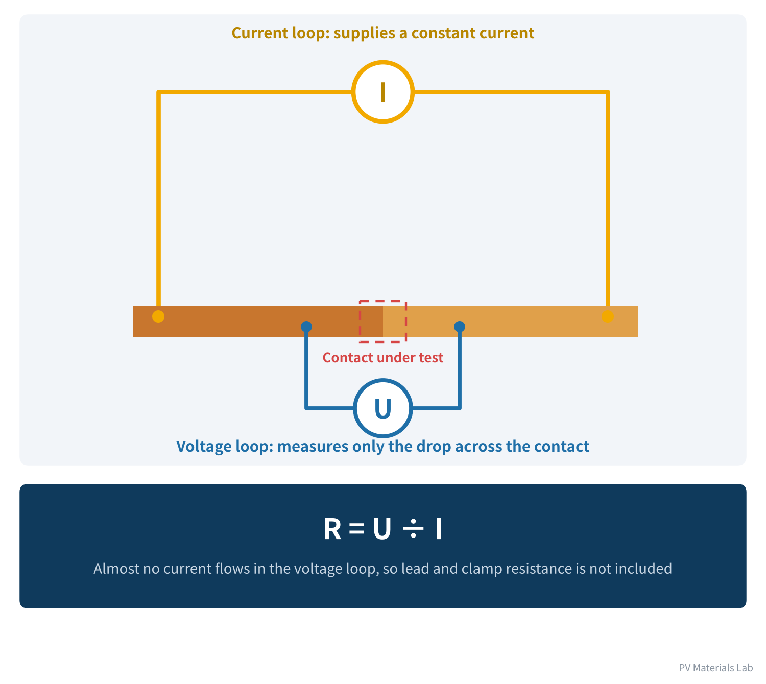
Figure 5 The four-wire method: measuring milliohm resistance accurately
The four-wire method separates "supplying current" and "measuring voltage" into two loops: one pair of leads supplies a constant current, the other pair measures only the voltage drop across the point under test. Almost no current flows in the voltage loop, so lead and clamp resistance is not included in the result.
Two principles of incoming inspection
- First check "is it the right thing", then check "is it good": Quietly swapped materials are a subtler risk than manufacturing defects. Whether model, marking and critical components match the certification file should come first.
- Test electrical properties widely, sample destructive items by risk: Fast, non-destructive tests such as forward voltage and circuit resistance can be sampled heavily; destructive items such as pull-out and sectioning are scheduled by batch risk.
05Process and outgoing inspection: after installation on the module
Once the junction box is installed, the object of inspection changes from "the junction box" to "the module with its junction box".
| Stage | Inspection items | Frequency |
|---|---|---|
| Installation | Sealant bead appearance and quantity, welding parameters, potting ratio | Every unit monitored or checked each shift |
| Installation | Weld pull force, cure state of adhesives | Regular sampling |
| Before shipping | Dielectric withstand, I-V characteristics, electroluminescence | Every module |
| Before shipping | Wet leakage, junction box adhesion strength | Per sampling plan |
Table 3 Process and outgoing inspection at the module end
The pre-shipment I-V test can catch obvious abnormalities such as a shorted diode — a shorted diode costs the module about a third of its open-circuit voltage.
An open-circuit diode cannot be seen in a routine I-V test: without shading the diode does not conduct anyway, so whether it is open makes no difference to the curve. Finding it requires a dedicated diode functionality test, such as method B of IEC 61215 MQT 18.2 — shade part of the cells and check that the I-V curve shows the normal step. As Article 3 explained, open-circuit failure is precisely the more dangerous kind; Kiwa PVEL checks diode function after thermal cycling and mechanical stress sequences, and in its 2026 Scorecard 17% of participating manufacturers had at least one failed bypass diode.
06Three misconceptions when reading test results
- "It has a certificate, so it's fine." A certificate proves that the submitted samples' design and materials passed; it does not guarantee that every production batch matches those samples. Consistency is safeguarded by incoming inspection and periodic sampling.
- "It tested well at room temperature." Junction box risks concentrate at high temperature: diode leakage, plastic strength and contact spring force all worsen as temperature rises. Good room-temperature data are only a starting point.
- "Every individual test passed." A new sample passing each test separately does not mean it will pass after sequential ageing. Ask what preconditioning the result was obtained after.
Beyond the standard tests, many buyers also require extended testing — Kiwa PVEL's PQP, for example, raises thermal cycling from 200 to 600 cycles and damp heat from 1,000 to 2,000 hours. The logic is that standard tests are only a threshold; only by increasing stress can the differences in margin between products be seen.
07Final thoughts
1. Junction box testing has three tiers — type testing, incoming inspection, and process and outgoing inspection — each answering one question.
2. The core logic of type testing is "age first, then test safety"; look at sequences, not isolated tests.
3. Wet leakage is the most sensitive overall check; sealing and potting defects cannot escape it.
4. Incoming inspection checks consistency first, then quality; milliohm resistance needs the four-wire method.
5. An open-circuit diode is a blind spot of routine I-V testing and needs a dedicated functionality test.
6. A certificate, room-temperature data and individual passes are not the same as "reliable".
That completes the "manufacturing and quality" part: how junction boxes are made, installed and tested. The next part, "standards and reliability", systematically reviews the standards and certifications mentioned throughout these articles.
In the next article, Junction Box Series 8 introduces certification: what IEC 62790, IEC 62852 and UL standards each cover, and how TÜV, UL and CQC certification differ.
Have you met cases in junction box testing where every individual test passed but the sequence failed? We would be glad to hear from you.
References
- IEC 62790:2020 Junction boxes for photovoltaic modules – Safety requirements and tests
- IEC 61215-2:2021 Terrestrial photovoltaic (PV) modules – Design qualification and type approval – Part 2: Test procedures
- IEC 61730-2 Photovoltaic (PV) module safety qualification – Part 2: Requirements for testing
- IEC 62979:2017 Photovoltaic modules – Bypass diode – Thermal runaway test
- IEC 60529 Degrees of protection provided by enclosures (IP code)
- TÜV Rheinland: Junction box – Overview of check routine, https://www.tuv.com/content-media-files/master-content/services/products/0206-tuv-rheinland-photovoltaic-components/tuv-rheinland-check-routine-junction-box-for-pv-systems-en.pdf
- Sinovoltaics: IEC 61215 MQT 15: Wet Leakage Current Test for Solar Modules, https://sinovoltaics.com/learning-center/testing/iec-61215-mqt-15-wet-leakage-current-test-for-solar-modules/
- Kiwa PVEL: 2026 PV Module Reliability Scorecard – Failures, https://2026scorecardsbx.pvel.com/failure
A PV R&D and technology team with 10+ years of experience | In-depth technical knowledge sharing
Materials · Reliability · Failure Analysis · Standards & Certification · Products · Processes
Exploring AI + PV; collaboration welcome
Disclaimer:
1. Original content reflects the authors' personal views only, is for reference only and does not constitute investment advice.
2. Reposted and cited content is credited to its source, out of respect for original work.
3. Some content was produced with AI assistance (chart generation, data retrieval, concept explanations, etc.); the core framework and key content were written by our technical team and reviewed by people.
4. If anything is inaccurate or infringes your rights, please leave a message or contact us and we will deal with it.