
Junction Box Series 10 | What Does a Junction Box Go Through in 25 Years? Reliability Mechanisms Under Five Stresses
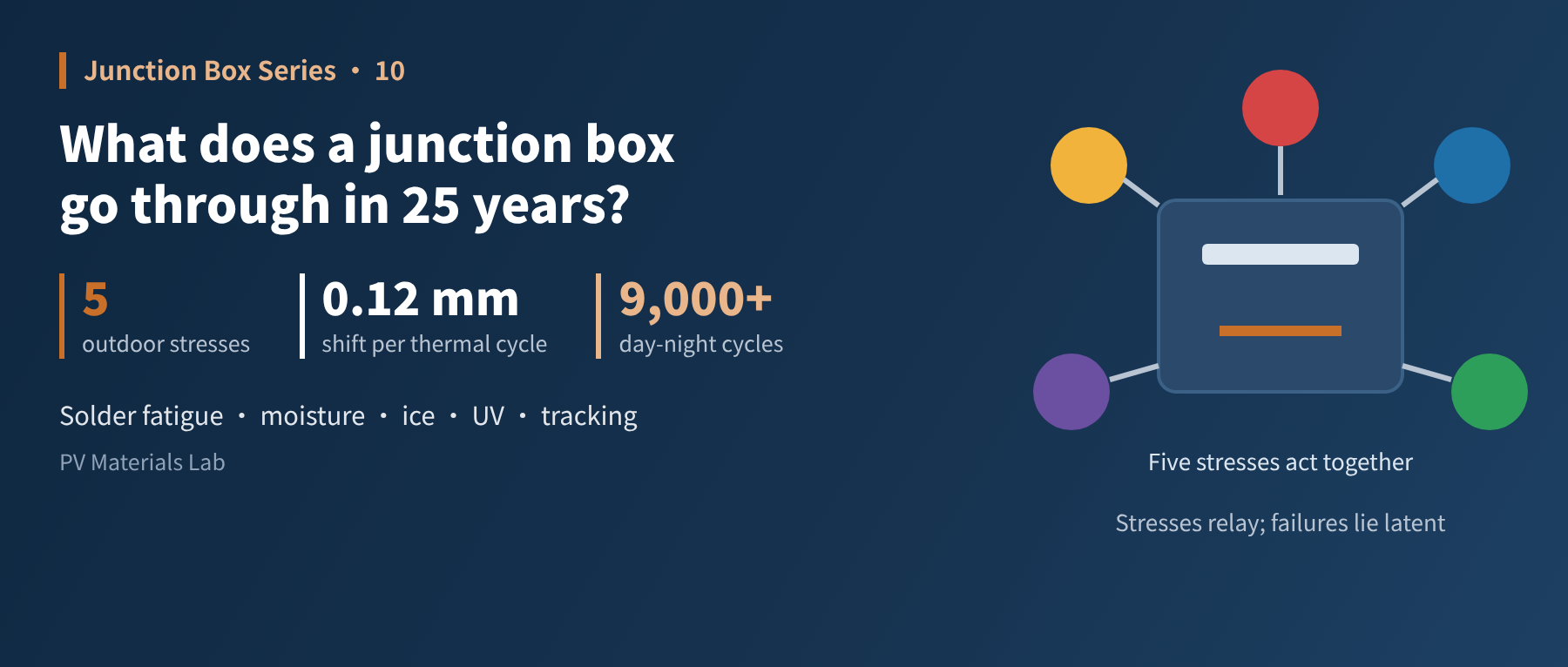
In brief
Thermal cycling pulls at solder joints, moisture hunts for gaps, UV ages the housing — passing certification is only the start. This article explains how a junction box gradually fails outdoors. This is the tenth article in our junction box series (Standards and Reliability: the junction box's key role in module reliability).
The last two articles were about certification. Certification answers "is this design qualified?". It is a threshold: once passed, it is passed.
Reliability asks a different question: time. What happens to a junction box that was fully compliant when it left the factory, after ten or twenty years in sun and rain? Module warranties run 25 to 30 years, and the junction box has to last the whole distance.
This article is not about clauses in standards but about mechanisms: which stresses exist outdoors, what each does to the junction box, and how they team up.
01Five stresses, all at once
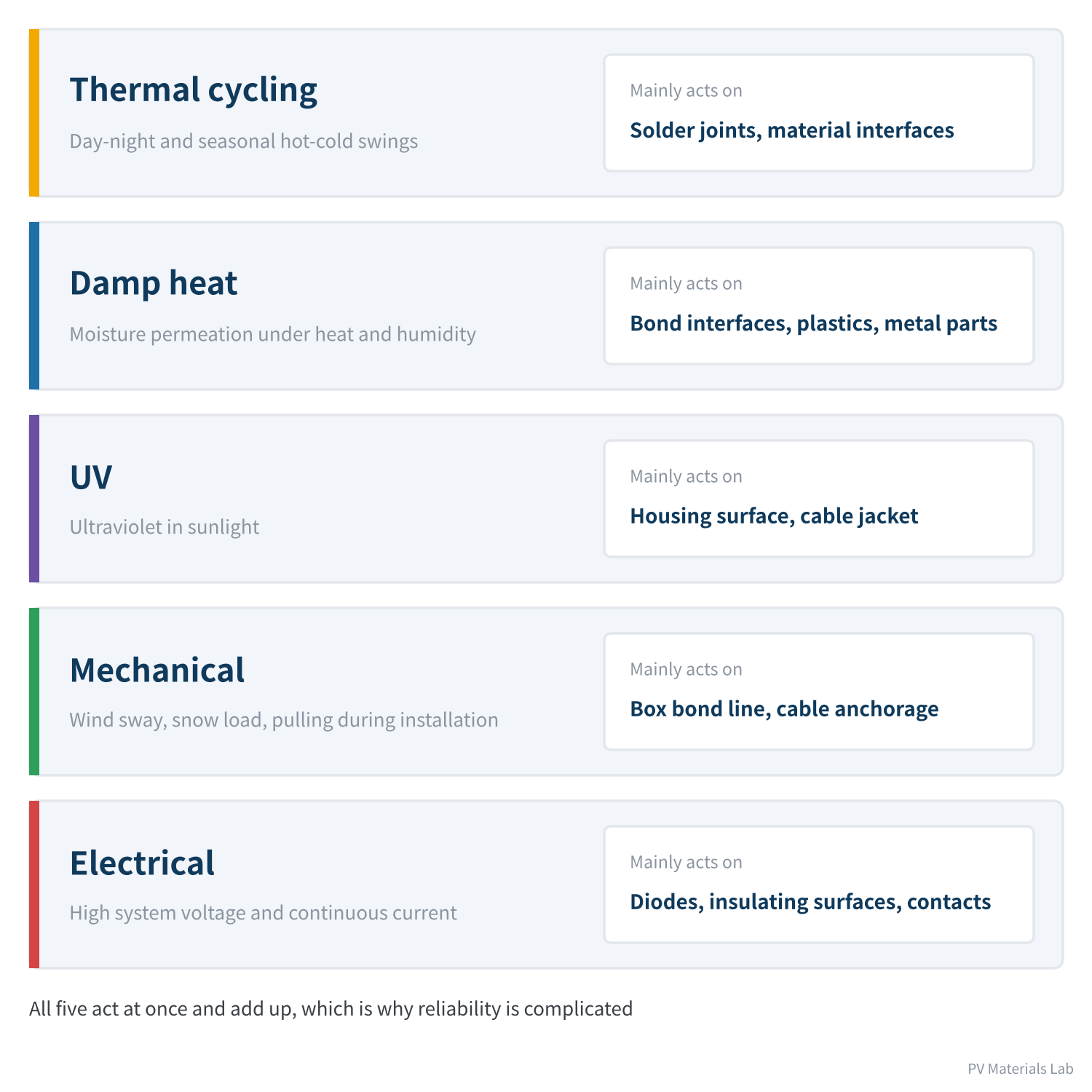
Figure 1 The five outdoor stresses and where they act
Each laboratory reliability test — thermal cycling, damp heat, humidity freeze, UV — isolates one outdoor stress and applies it in accelerated form. Understand the stress itself and you understand what the test is examining.
Let us take them one at a time.
02Thermal cycling: a tug every day
No material in a junction box stands alone. When the temperature changes, each expands or contracts in its own way, yet they are all fixed together.
Materials expand when heated and contract when cooled, and the amount differs widely between materials. The measure of this is the coefficient of thermal expansion (CTE).
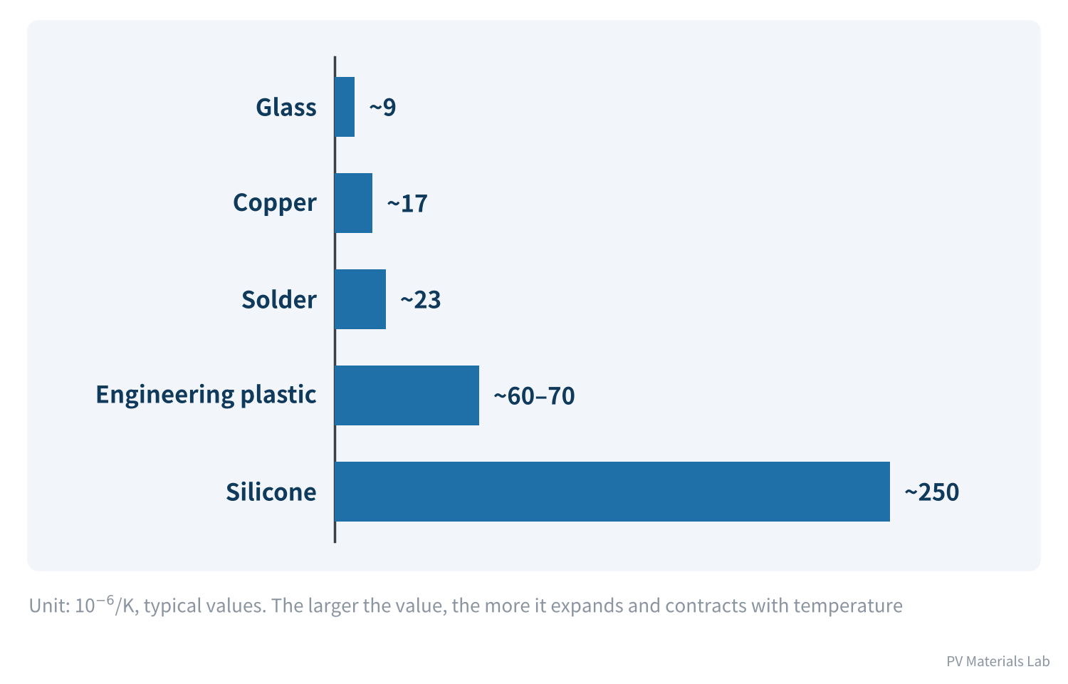
Figure 2 Coefficients of thermal expansion of materials in a junction box
A junction box is exactly where these materials with very different "tempers" are locked together: copper terminals clip into a plastic base, ribbons are soldered to the copper terminals, silicone encases it all, and the whole box is bonded to glass or backsheet.
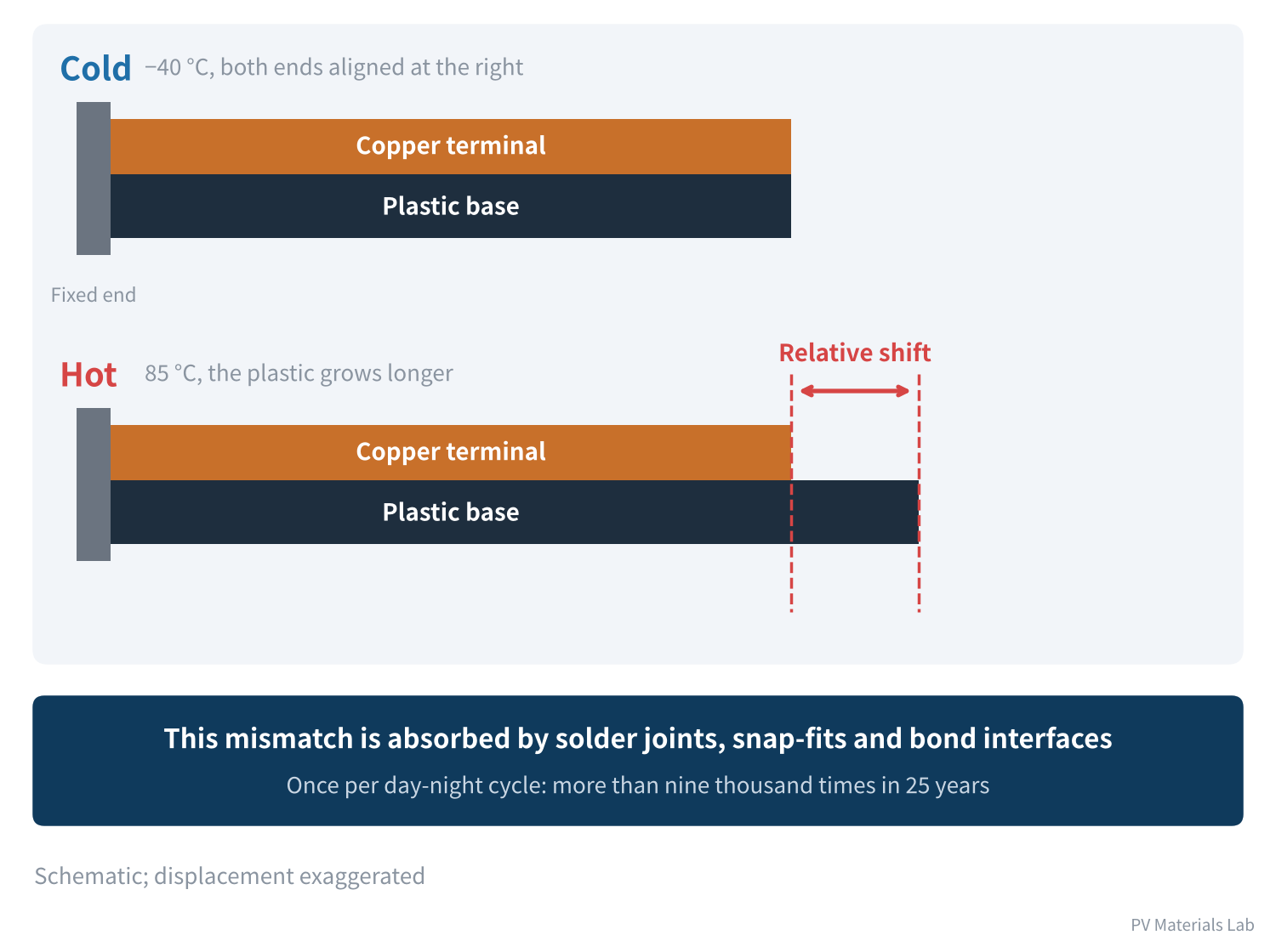
Figure 3 Between cold and hot, copper and plastic move different distances
Take a 20 mm length of copper terminal clipped into a plastic base. Copper's CTE is about 17 and the plastic's about 65, a difference of 48 (in 10⁻⁶/K).
The thermal cycling test runs from −40 °C to 85 °C, a span of 125 °C:
20 × 48 × 10⁻⁶ × 125 ≈ 0.12 mm
0.12 mm sounds negligible, but it has to be absorbed by solder joints and snap-fits, and it happens every cycle.
Outdoors the temperature swing is less extreme than in a test chamber, but there are far more cycles. At one day-night cycle a day, 25 years means more than nine thousand cycles (25 × 365 ≈ 9,125), whereas IEC 61215 thermal cycling is 200 cycles and extended third-party testing such as Kiwa PVEL's goes to 600. Under repeated small deformations, metals and solder gradually fatigue: cracks start at microscopic defects and grow bit by bit.
Thermal cycling attacks three places first:
- Solder joints: between ribbons and terminals, and between diodes and terminals. Joints that were already poorly soldered crack first.
- Interfaces: the bond between potting compound and housing, and between potting compound and cables. Silicone's CTE is several times that of the plastic, so these interfaces are under constant shear.
- Weak points in the housing: weld lines left by injection moulding and sharp corners, where cracks begin.
Thermal cycling often does not cause failure directly. What it does is "open the door": crack a solder joint slightly, tear an interface open a little, and leave the rest to the other stresses.
03Damp heat: water always finds a way
The goal of waterproofing has never been to keep out every single water molecule, but to stop liquid water from collecting and water vapour from doing damage.
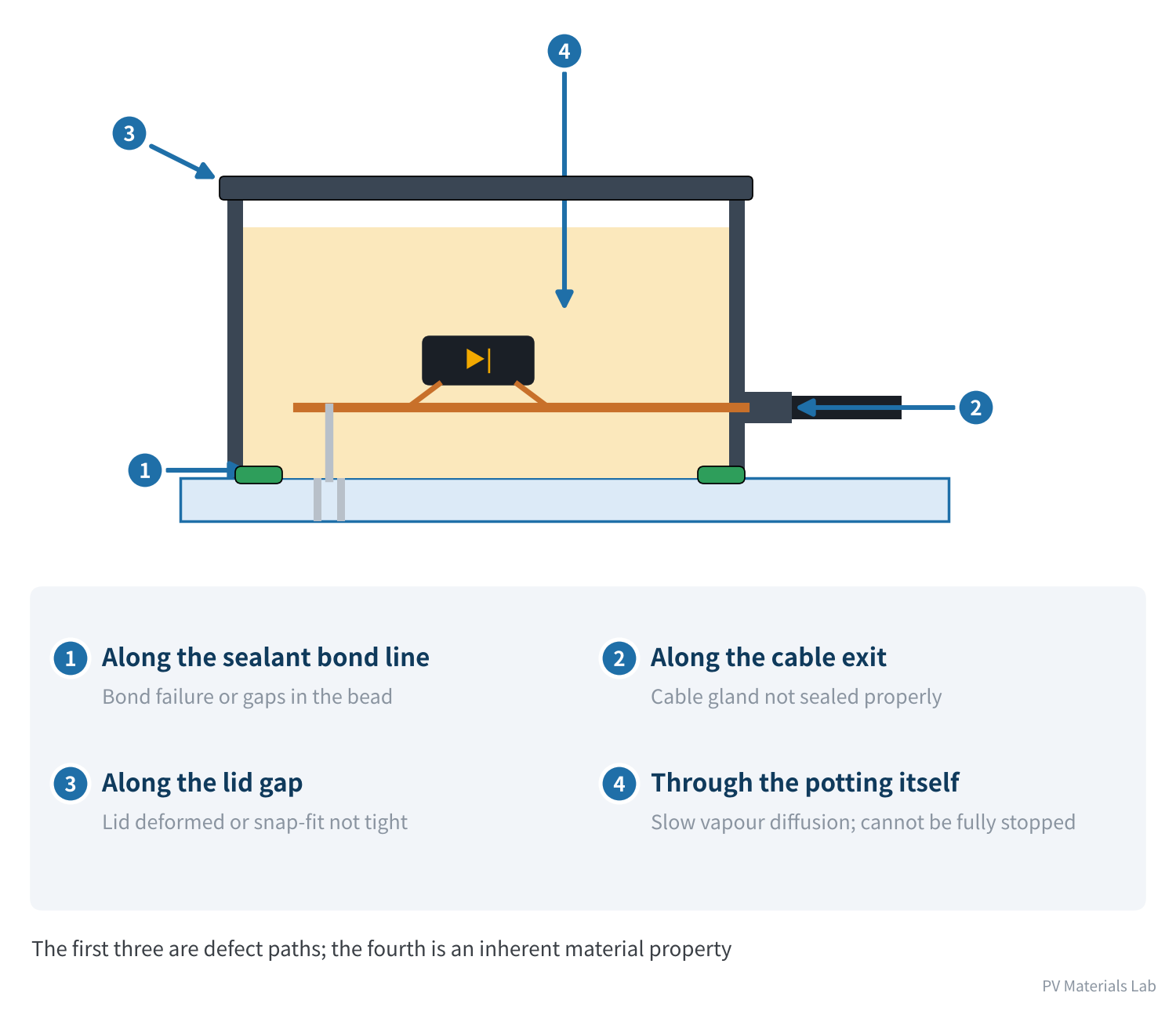
Figure 4 How water gets into a junction box
Water has four ways into a junction box. The first three — along the sealant bond line, along the cable exit, and along the lid gap — are channels created by defects, which design and process can close.
The fourth cannot be closed. Silicone has an easily overlooked property: it blocks liquid water well but does not stop water vapour. Water molecules slowly diffuse through the material itself. Given enough time, the humidity inside the box will approach that outside.
So the real defence is not "isolation" but three things:
- No voids: potting fills the cavities, so even if vapour gets in, there is nowhere for it to condense into liquid water.
- Strong interfaces: when vapour reaches an interface, the bond must be strong enough to resist it, so the interface is not "soaked open".
- Water-resistant materials: a housing plastic that does not hydrolyse, plated metal surfaces, and no corrosive residues such as flux.
What water does once inside
| Affected part | What happens | Consequence |
|---|---|---|
| Bond interface | Water molecules penetrate the interface and weaken adhesion | Box lifts, gaps widen |
| Plastic housing | Some materials hydrolyse and embrittle under damp heat | Strength drops, cracking becomes easier |
| Metal parts | Corrode under water and residues together | Contact resistance rises |
| Insulating surfaces | Moisture plus contaminants form leakage paths | Insulation resistance drops, leakage to ground |
Table 1 What moisture does inside a junction box, and the consequences
As we said in article 2 on materials, one important reason for choosing modified PPO for the housing is its low water absorption and resistance to hydrolysis. The value of that choice only shows up in damp heat.
04Humidity freeze: turning small gaps into big ones
Humidity freeze is damp heat's accomplice. Water expands by about 9% when it freezes.
If vapour has already condensed in a tiny gap, then when the temperature drops below zero, ice forces the gap open a little. After thawing, more water enters the larger gap; the next freeze pushes it open a bit further. After a few winters, an interface defect that was invisible to the eye can grow into a through-channel.
That is why, in the IEC 61215 test sequence, humidity freeze comes after UV preconditioning and 50 thermal cycles: let thermal cycling open the gaps and moisture get in first, then freeze it.
05UV: ageing from the surface
The junction box sits on the back of the module, out of direct sunlight, but it cannot avoid light reflected from the ground and scattered from the sky. The higher a bifacial module is mounted and the more reflective the ground, the more UV reaches the rear. IEC 61215:2021 already requires rear-side UV preconditioning for bifacial modules, and the extended sequences in IEC TS 63209-1 specifically include rear-side UV.
UV breaks the molecular chains of plastics. The parts most affected are those exposed to it:
- Housing surface: gradually fades and chalks; the surface layer embrittles and develops microcracks under mechanical stress.
- Cable jackets and connector housings: more exposed than the box itself, and the main targets of UV ageing.
UV ageing works from the surface inwards and on its own is often just cosmetic. But surface microcracks become starting points for crack growth under thermal cycling, and they make it easier for water to cling and penetrate.
06Mechanical: the most underestimated
- Pulling on cables: carrying modules by their cables during installation and yanking on them when routing are common on site. If the cable anchorage does not stop these forces, they reach the solder joints.
- Long-term wind sway: loose cables and connectors swinging in the wind put continuous fatigue loading on the cable-exit seal and on connector contact surfaces.
- Module bending: wind and snow loads bend the module, but the junction box is rigid. The bond line between box and module must absorb this difference, and its edges see repeated peel forces.
Mechanical stress is closely tied to installation quality. The same batch of junction boxes can have very different lifetimes in a well-installed plant and in one built carelessly.
07Electrical: stress the box creates itself
The four stresses above come from the environment. The fifth comes from the junction box's own operation.
- Diode heating: on modules permanently shaded by chimneys, poles or neighbouring buildings, the diodes conduct for several hours every day. Article 3 covered how much heat they generate when conducting; long periods at high temperature speed up the ageing of the diode and the materials around it.
- Contact heating: as calculated in articles 1 and 4, once contact resistance increases, heating grows with the square of the current, and the heat in turn makes the contact worse.
- Leakage at high voltage: junction boxes operate at system voltages up to 1500 V. Once an insulating surface gets damp and collects contaminants, small surface discharges can occur, leaving conductive carbonised tracks (tracking) that steadily destroy the insulation.
Potential-induced degradation (PID) is often mentioned alongside junction box problems because the field symptoms look similar: both involve high voltage and moisture, and both may come with abnormal insulation to ground. But the mechanisms differ. PID occurs mainly at the cell and encapsulant level, and the junction box is not its main cause. Ground leakage caused by a failed junction box seal should be investigated as a separate problem.
08The real problem: stresses work as a relay
We separated the five stresses to explain them clearly. Outdoors, they never act separately.
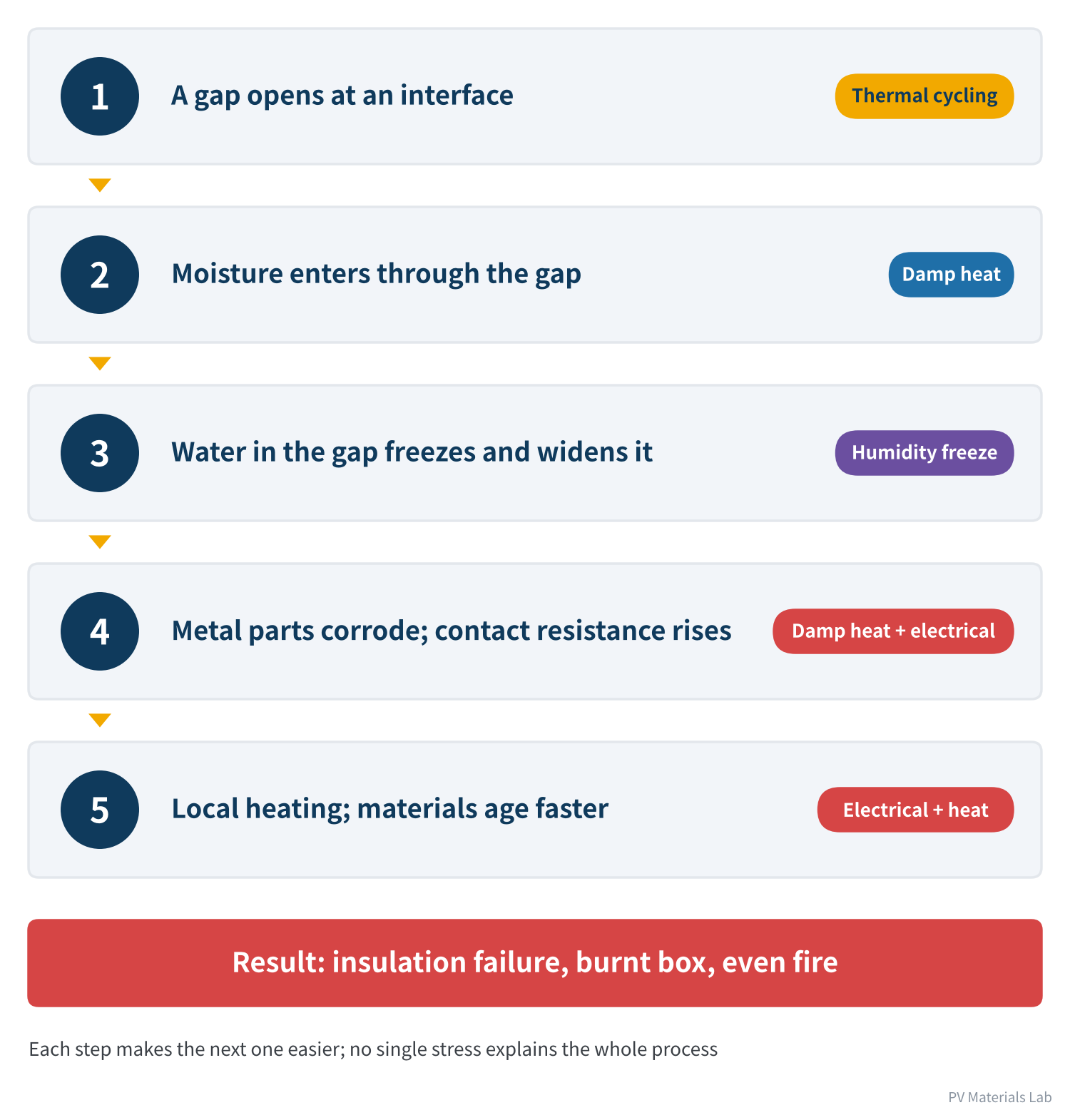
Figure 5 A stress relay: a typical failure chain
No single step in this chain is fatal on its own: a hairline gap affects no function, and a little moisture does not cause an immediate fault. But each step makes the next more likely, and in the second half the process accelerates itself: heat speeds up ageing, and ageing makes the heating worse.
This explains two things:
- Why reliability tests are run as sequences: in article 7 we described "age first, then test safety". Thermal cycling alone or damp heat alone cannot reproduce this relay. The extended sequences in IEC TS 63209-1:2021 (600 thermal cycles, 2,000 hours of damp heat, a combined sequence of rear-side UV with humidity freeze and thermal cycling, and others) exist to compare bills of materials over longer time scales.
- Why field failures often have a latency period: junction box problems tend to surface in clusters after several years of operation. The early steps of the chain happen quietly; by the time something can be seen or measured, the process is already in its second half.
Third-party extended testing bears this out. In Kiwa PVEL's 2026 PV Module Reliability Scorecard, 21% of participating manufacturers had junction box-related failures, 9% had junction box wet-leakage safety failures and 4% had lids come off; 17% had bypass diode failures. Kiwa PVEL's sequences are themselves harsher than certification (for example 600 thermal cycles and 2,000 hours of damp heat), precisely so that latent problems surface early.
09Looking back at design and process through mechanisms
With the stresses understood, every design choice and process control from the earlier articles has a clear adversary:
| Stress | Weak points | Corresponding design and process |
|---|---|---|
| Thermal cycling | Solder joints, interfaces | Reliable soldering, good bonding between potting and housing |
| Damp heat and humidity freeze | Interfaces, metal parts | Closed adhesive bead, fully filled potting, no flux residue, hydrolysis-resistant materials |
| UV | Housing surface, cables | Weather-resistant housing materials and cable jackets |
| Mechanical | Bond line, cable anchorage | Reliable cable anchorage, proper installation and cable fixing |
| Electrical | Diodes, contacts | Ample thermal design margin, low and stable contact resistance |
Table 2 Five stresses, their weak points, and the corresponding design and process
Reliability is not guaranteed by one "good material" or one "critical process step". It comes from every link leaving no entry point for stress.
10Final thoughts
1. Outdoors, a junction box faces five stresses at once: thermal cycling, damp heat, UV, mechanical and electrical.
2. Thermal cycling comes from differences in CTE; it acts mainly on solder joints and interfaces and "opens the door" for other stresses.
3. Silicone does not stop water vapour; the real defence is no voids, strong interfaces and water-resistant materials.
4. Humidity freeze widens small gaps, UV creates crack starting points on surfaces, and mechanical stress depends heavily on installation quality.
5. The box's own heating and high voltage make up the fifth stress.
6. The five stresses act as a relay, forming a self-accelerating failure chain; this is why field failures have a latency period.
That completes the three "Standards and Reliability" articles: the certification system, assessment in module certification, and reliability mechanisms. Mechanisms explain how things might fail; the next article looks at how they actually failed.
In the next article, Junction Box Series 11 looks at typical failure cases and failure analysis: diode breakdown, burnt boxes, uncured potting and water ingress from failed seals, each broken down by symptom, mechanism, root cause and countermeasure.
What junction box problems have you seen that only appeared after several years in the field? We would be glad to hear from you.
References
- IEC 61215-1:2021, IEC 61215-2:2021 Terrestrial photovoltaic (PV) modules – Design qualification and type approval
- IEC 62790:2020 Junction boxes for photovoltaic modules – Safety requirements and tests
- IEC 61730-2:2023 Photovoltaic (PV) module safety qualification – Part 2: Requirements for testing
- IEC TS 63209-1:2021 Photovoltaic modules – Extended-stress testing – Part 1: Modules, https://assets.vde-verlag.de/iec-normen/preview-pdf/info_iects63209-1%7Bed1.0%7Den.pdf
- Intertek: UL 61215-2 Standards Update Notice (including rear-side UV for bifacial modules), https://www.intertek.com/siteassets/resources/sun/2024/ul-61215-2-sun-rev-7-28-2021-ed-4-1-2025-amendment-1.pdf
- Kiwa PVEL: 2026 PV Module Reliability Scorecard – Failures, https://2026scorecardsbx.pvel.com/failure
A PV R&D and technology team with 10+ years of experience | In-depth technical knowledge sharing
Materials · Reliability · Failure Analysis · Standards & Certification · Products · Processes
Exploring AI + PV; collaboration welcome
Disclaimer:
1. Original content reflects the authors' personal views only, is for reference only and does not constitute investment advice.
2. Reposted and cited content is credited to its source, out of respect for original work.
3. Some content was produced with AI assistance (chart generation, data retrieval, concept explanations, etc.); the core framework and key content were written by our technical team and reviewed by people.
4. If anything is inaccurate or infringes your rights, please leave a message or contact us and we will deal with it.