
Junction Box Series 11 | How Do Junction Boxes Fail? Symptoms, Mechanisms, Root Causes and Countermeasures for Six Typical Failures
In brief
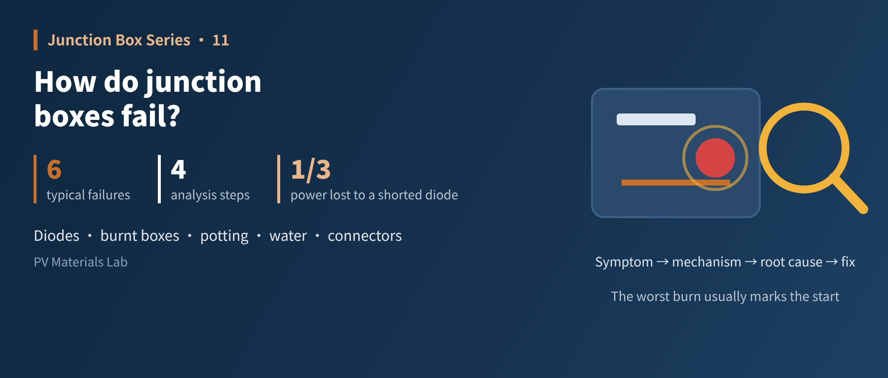
Diode short and open circuits, burnt boxes, potting anomalies, water ingress and burnt connectors — six typical failures broken down one by one, plus a general method for failure analysis. This is the eleventh article in our junction box series (Standards and Reliability: typical failure cases and failure analysis).
The last article was about mechanisms: how a junction box might fail under five stresses. This one is about outcomes: the forms in which it actually fails.
Every "if it is not done well" planted in the previous ten articles — insufficient diode thermal margin, cold solder joints, gaps in the adhesive bead, cross-mated connectors — eventually comes due here as some kind of failure.
This article first sets out a method, then takes the six typical failures apart one by one: what you see, the mechanism behind it, where the root cause usually lies, and how to prevent it.
What we describe are failure types common in the industry, generalised as "typical situations". They do not correspond to any specific project, company or product. Real failure analysis must rest on physical evidence.
01Method first: four steps of failure analysis
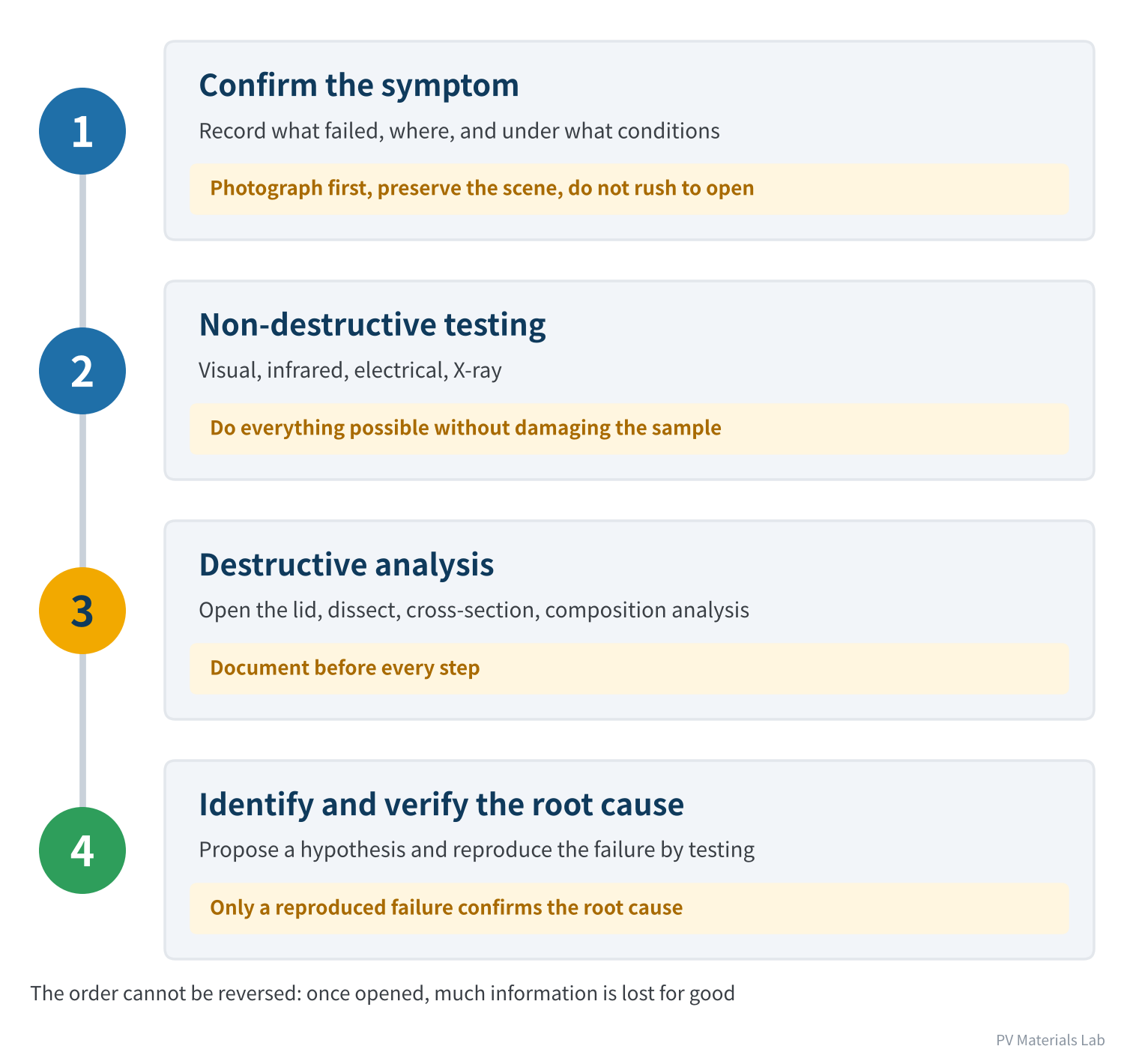
Figure 1 Four steps of failure analysis
The order of these four steps cannot be reversed. The most common mistake in failure analysis is to open up a failed part straight away — once it is opened, a lot of information is lost for good: whether the lid was ever properly snapped shut, what the adhesive surface originally looked like, and where exactly the hot spot was before disassembly.
Two more principles are easily overlooked:
- Always keep a reference sample: find a good part from the same batch and run the same tests on it as on the failed one. Without a reference, you cannot tell whether what you see is abnormal or simply how it always is.
- Distinguish the origin from the consequences: inside a burnt junction box everything is black, and the diode, terminals and plastic are all damaged. What you are really looking for is the first point that went wrong; everything else follows from it.
02Overview of the six typical failures
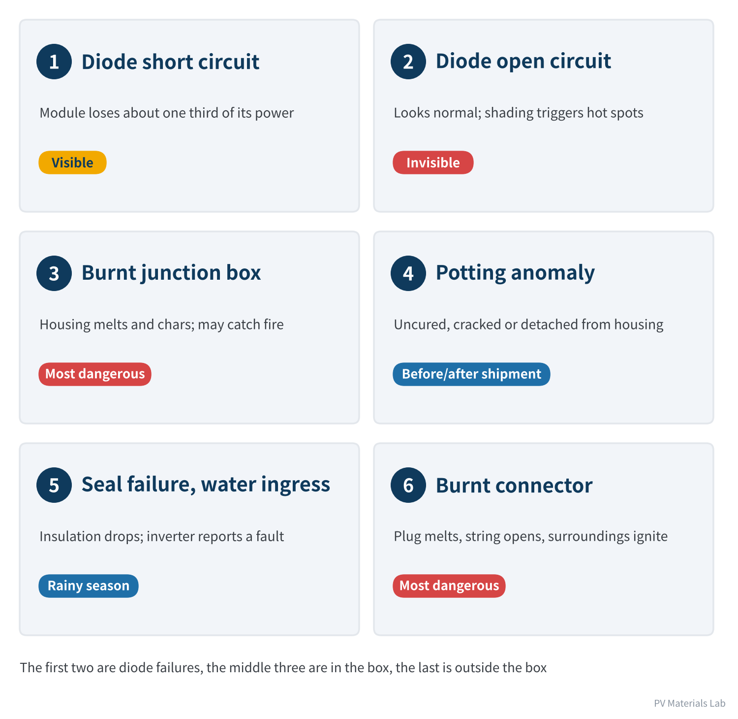
Figure 2 Six typical failures of the junction box system
These failures are not rare. In Kiwa PVEL's 2026 PV Module Reliability Scorecard, 17% of participating manufacturers had at least one bypass diode failure and 21% had junction box-related failures (including 9% with junction box wet-leakage safety failures and 4% with lids coming off).
03Two diode failures
Failure ①: diode short circuit
| Item | Details |
|---|---|
| Symptom | Module power drops by about one third; I-V testing shows open-circuit voltage about one third lower; the junction box may stay warm under infrared |
| Mechanism | After breakdown, the diode chip conducts at low resistance and shorts out the substring it protects; the power from that substring is consumed internally |
| Common root causes | Thermal runaway; thermal fatigue from long periods at high temperature; surge voltage induced by lightning; electrostatic damage during production or installation |
| Countermeasures | Leave enough junction-temperature margin when selecting diodes and verify thermal runaway; ESD protection throughout; lightning and surge protection on the system side; avoid long-term fixed shading at the design stage |
Table 1 Failure ①: diode short circuit
Failure ②: diode open circuit
| Item | Details |
|---|---|
| Symptom | Nothing abnormal day to day; power and I-V curve both look normal; when partial shading occurs, the shaded cells overheat severely |
| Mechanism | The diode circuit is broken and bypass protection is lost. The shaded cell has to withstand the reverse voltage of the whole substring or more, and the hot spot loses its "cap" |
| Common root causes | Diode solder joints crack under thermal cycling; leads break; the diode burns open internally after an overcurrent |
| Countermeasures | Control soldering quality and solder voids; test diode function before shipment; spot-check periodically in O&M with the shading method or dedicated instruments |
Table 2 Failure ②: diode open circuit
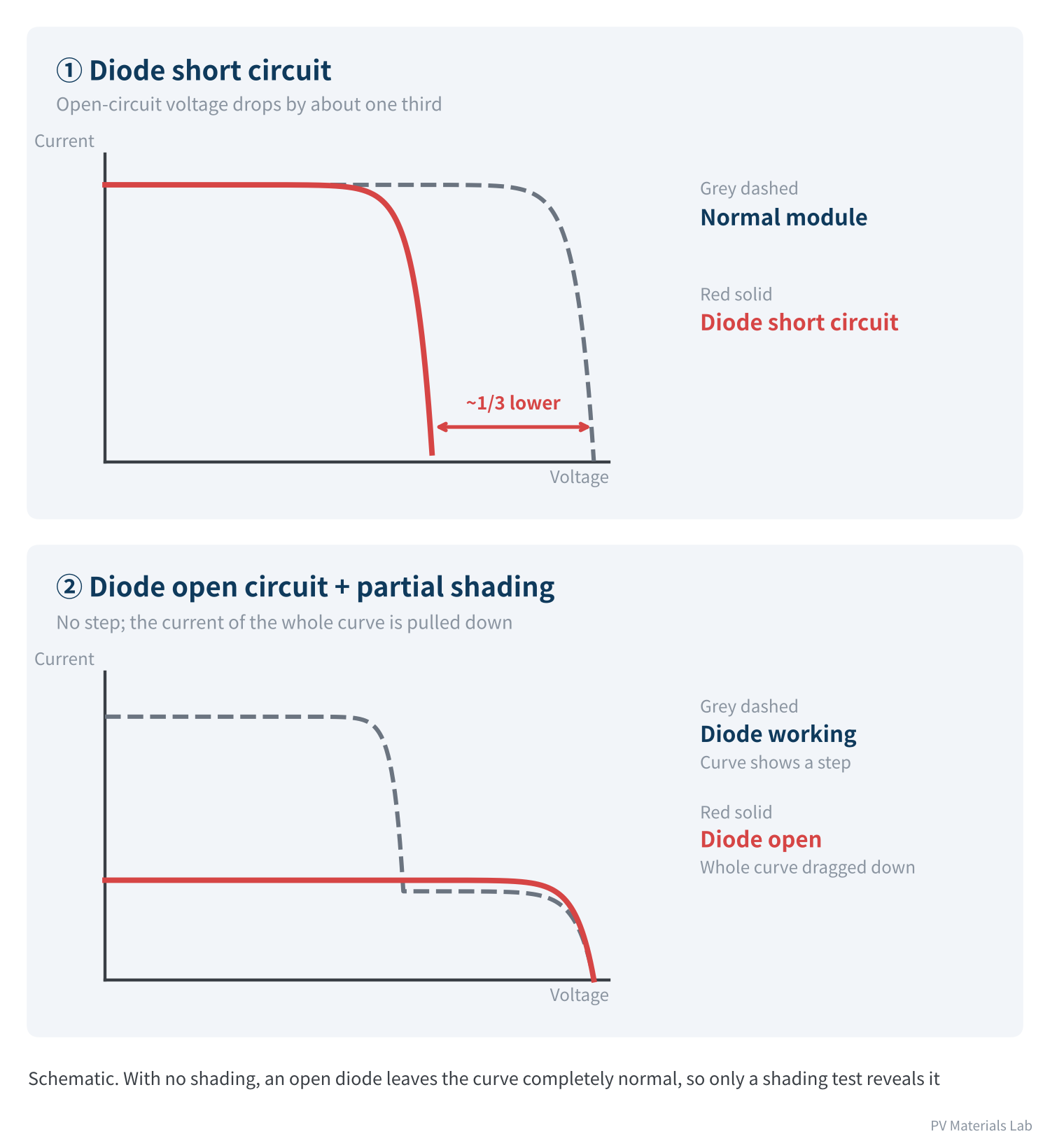
Figure 3 What diode failures look like on the I-V curve
The two failures are very different to detect. A short circuit is written directly on the I-V curve and is found as soon as you measure. An open circuit is completely invisible in routine testing; the only way to find it is to create shading deliberately and check whether the expected "step" appears on the curve.
Field methods for detecting open diodes are improving. Public presentation material from IEA-PVPS Task 13 in 2025 describes a night-time method: apply a reverse voltage to a string at night. Normally the current flows through the diodes and the voltage stays low; if a substring's diode is open, that substring has to be "broken down" to conduct and the voltage rises by roughly 300–600 V. This allows strings to be screened without removing modules.
What makes an open-circuit failure dangerous is that it quietly turns a protected system into an unprotected one, with no warning at all.
04Three failures of the box
Failure ③: burnt junction box
| Item | Details |
|---|---|
| Symptom | Housing locally melted, bulging, charred black; scorch marks on the backsheet or glass behind it; fire in severe cases |
| Mechanism | One point inside the box keeps heating abnormally beyond what can be dissipated, gradually scorching the surrounding plastic and potting; charred material conducts and may lead to arcing |
| Common root causes | Cold solder joints on ribbons; poor terminal contact; diodes conducting for long periods with insufficient cooling; continued heating after a diode short; corrosion after water ingress raising contact resistance |
| Countermeasures | Control the soldering process and monitor parameters; leave enough diode thermal margin; make sure potting is complete; use infrared inspection in O&M to find overheating before it burns |
Table 3 Failure ③: burnt junction box
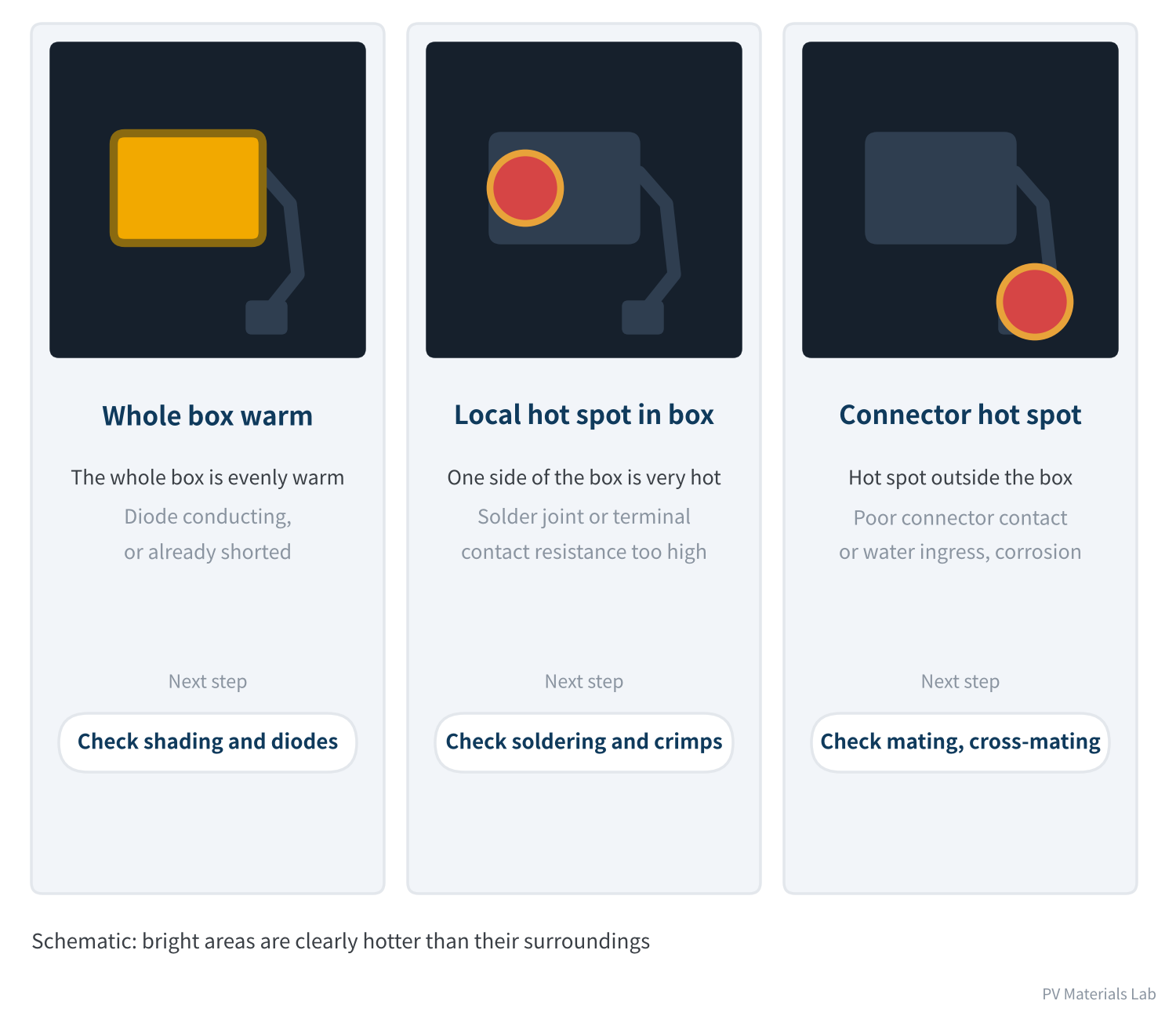
Figure 4 Three heating patterns under infrared imaging
Burning is a result, not a cause. Upstream there may be five or six different problems. In the analysis, lay out every possibility first, then rule them out one by one with evidence.
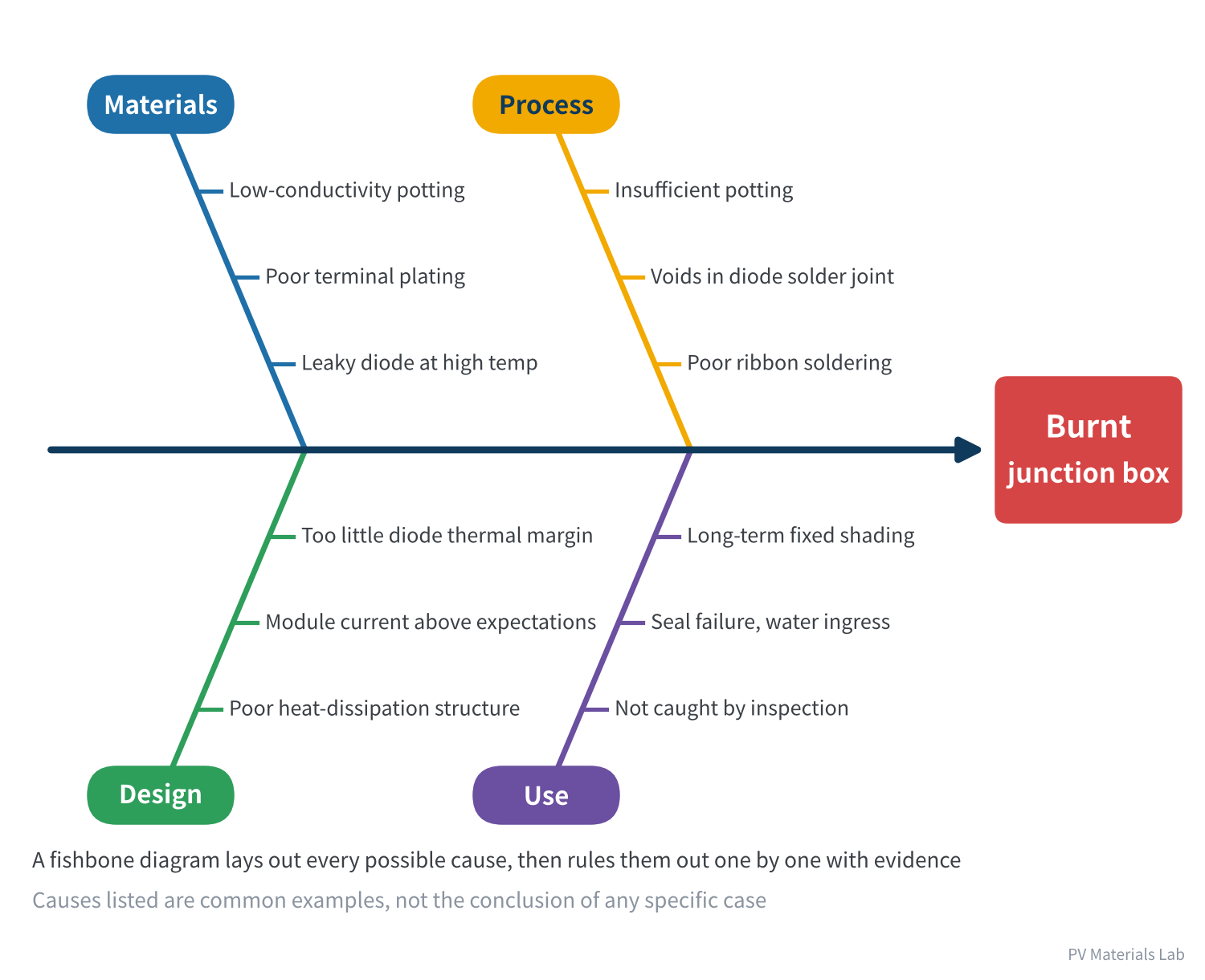
Figure 5 Root-cause fishbone diagram for a burnt junction box
There is a practical clue for finding the origin: the most heavily burnt spot is usually where the heating started. If the damage is concentrated where the ribbon joins the terminal, suspect the soldering first; around the diode, suspect the diode; at the cable entry, suspect the crimp or cable connection.
Failure ④: potting anomaly
| Item | Details |
|---|---|
| Symptom | Potting stays tacky and uncured; potting cracks; gaps between potting and housing or cables; obvious discolouration |
| Mechanism | Uncured potting means the curing reaction did not complete; cracking and detachment come from shrinkage, thermal expansion and contraction, and insufficient interface adhesion acting together |
| Common root causes | Wrong mix ratio or poor mixing; addition-cure silicone "poisoned" by flux residues and similar substances; incomplete cure at low temperature and humidity; incompatibility between potting and housing material; air trapped during potting |
| Countermeasures | Check the mix ratio every shift and keep retained samples; verify compatibility before changing any related material; specify and record curing conditions; prefer soldering methods without flux |
Table 4 Failure ④: potting anomaly
Potting problems have one characteristic: uncured potting is usually found before shipment, while cracking and detachment appear only after hot-cold cycling outdoors. The former is a process problem; the latter usually traces back to material matching.
Failure ⑤: seal failure and water ingress
| Item | Details |
|---|---|
| Symptom | Inverter reports low insulation resistance, especially after rain or in the early morning; wet leakage test fails; water marks, rusted metal parts or whitened potting visible once opened |
| Mechanism | Water enters the box through channels created by defects, forming a conductive path between live parts and the outside, while corroding metal parts |
| Common root causes | Gaps in the sealant bead or too little sealant; box moved under force before the adhesive cured; cable gland not tightened; potting not covering live parts; deformed lid |
| Countermeasures | Ensure a closed bead with visible squeeze-out; avoid loading before cure; sample wet leakage testing before shipment; keep cables from being pulled during installation |
Table 5 Failure ⑤: seal failure and water ingress
Water ingress is hard to track down for one reason: the fault is intermittent. On a fine day, once modules dry out, insulation may recover and the fault disappears. Investigate such problems in damp conditions, or test after spraying water deliberately.
05Failures outside the box
Failure ⑥: burnt connector
| Item | Details |
|---|---|
| Symptom | Connector housing melted, deformed or charred; open string; in severe cases nearby cables, backsheet or roofing ignite |
| Mechanism | Rising contact resistance causes continuous heating, which in turn degrades the contact surfaces faster; when contact finally breaks, a DC arc may be drawn |
| Common root causes | Cross-mating different brands; improper field crimping; not fully mated; water or sand inside before mating; unsecured cables swinging for long periods |
| Countermeasures | Lock in the same manufacturer and model across the site; use dedicated crimping tools; cap unmated connectors; secure cables; infrared inspection |
Table 6 Failure ⑥: burnt connector
We covered connectors in detail in article 4. Just one point to stress here: of the six failures, burnt connectors are the most closely tied to installation quality; the problem usually does not lie with the product itself.
Field data confirms how widespread it is. A 2025 study by the US inspection firm HelioVolta, based on more than 5 GW of field inspections, found that 83% of projects had at least one connector-related issue, 45% of sites had major connector issues requiring urgent maintenance, and 4.3% of projects had critical connector failures requiring partial or total de-energisation.
06One table: from symptom to direction
| What you see | Suspect first | Do first |
|---|---|---|
| About one third of power missing | Diode short circuit | Measure open-circuit voltage, check infrared |
| Cells overheat badly under partial shading | Diode open circuit | Shading test with I-V curve |
| Junction box clearly hot | Diode conducting, solder joint or terminal | Check hot-spot location in infrared, check for shading |
| Inverter insulation fault, worse after rain | Seal failure and water ingress | Measure insulation in damp conditions, string by string |
| Connector hot or deformed | Poor contact, cross-mating | Check brand, model and mating state |
| Potting tacky or cracked | Mix ratio, compatibility | Check retained samples and same-batch products |
Table 7 From symptom to direction of investigation
This table tells you where to look first, not what the conclusion is. The real root cause has to be confirmed step by step with evidence, using the method in section 1.
07What failures teach us
Put the root causes of the six failures side by side and some patterns emerge:
- Most failures start small: a cold solder joint, a break in the adhesive bead, a connector not fully mated — tiny defects present from manufacture or installation that become incidents only after long amplification by outdoor stresses.
- Interfaces fail more readily than bulk material: solder joints, bond lines, contact surfaces — failures almost always occur where two materials or two parts meet, not in the material itself.
- Heat is the common exit: whatever the origin, most serious failures end up as abnormal heating. That is why infrared inspection is so effective.
- Invisible failures are the most dangerous: an open diode or a slight shift before the adhesive cured gets past routine inspection; it takes dedicated methods to find them.
The value of failure analysis is not assigning blame for one incident, but feeding conclusions back into design, materials, process and installation so the same problem does not happen again.
08Final thoughts
1. Failure analysis runs in four steps — confirm the symptom, non-destructive testing, destructive analysis, identify and verify the root cause — and the order cannot be reversed.
2. A diode short circuit is visible and costs energy; an open circuit is invisible and removes hot-spot protection.
3. A burnt junction box is a result with many possible upstream causes; the most heavily burnt spot is usually the origin.
4. Uncured potting is mostly a process problem; cracking and detachment are mostly material-matching problems.
5. Water ingress faults are intermittent and should be investigated in damp conditions.
6. Burnt connectors are most closely tied to installation quality.
That completes all four "Standards and Reliability" articles. From the next article we enter the final part, "Market and Trends", with a different perspective: which companies make junction boxes, and what the industry looks like today.
In the next article, Junction Box Series 12 looks at the business performance and shipments of Chinese junction box suppliers: the main companies, the market structure and the changes under way in the industry.
In your failure analysis work, have you met cases where the origin and the consequences were hard to tell apart? We would be glad to hear from you.
References
- IEC 61215-2:2021 Terrestrial photovoltaic (PV) modules – Design qualification and type approval – Part 2: Test procedures
- IEC 62790:2020 Junction boxes for photovoltaic modules – Safety requirements and tests
- IEC 62979:2017 Photovoltaic modules – Bypass diode – Thermal runaway test
- IEC 62852:2014+AMD1:2020 Connectors for DC-application in photovoltaic systems – Safety requirements and tests
- Kiwa PVEL: 2026 PV Module Reliability Scorecard – Failures, https://2026scorecardsbx.pvel.com/failure
- Solar Power World: HelioVolta study: Solar connector failures remain major threat to systems (2025-06-18), https://www.solarpowerworldonline.com/2025/06/heliovolta-study-solar-connector-failures-remain-major-threat-to-systems/
- IEA-PVPS Task 13: Failures in current PV systems and their relevance to find them (2025), https://iea-pvps.org/wp-content/uploads/2025/08/02_Koentges_Failures-in-current-PV-systems-and-their-relevance-to-find-them.pdf
A PV R&D and technology team with 10+ years of experience | In-depth technical knowledge sharing
Materials · Reliability · Failure Analysis · Standards & Certification · Products · Processes
Exploring AI + PV; collaboration welcome
Disclaimer:
1. Original content reflects the authors' personal views only, is for reference only and does not constitute investment advice.
2. Reposted and cited content is credited to its source, out of respect for original work.
3. Some content was produced with AI assistance (chart generation, data retrieval, concept explanations, etc.); the core framework and key content were written by our technical team and reviewed by people.
4. If anything is inaccurate or infringes your rights, please leave a message or contact us and we will deal with it.