
Junction Box Series 14 | What Makes a Smart Junction Box Smart? Shutdown, Optimisation and Monitoring Explained
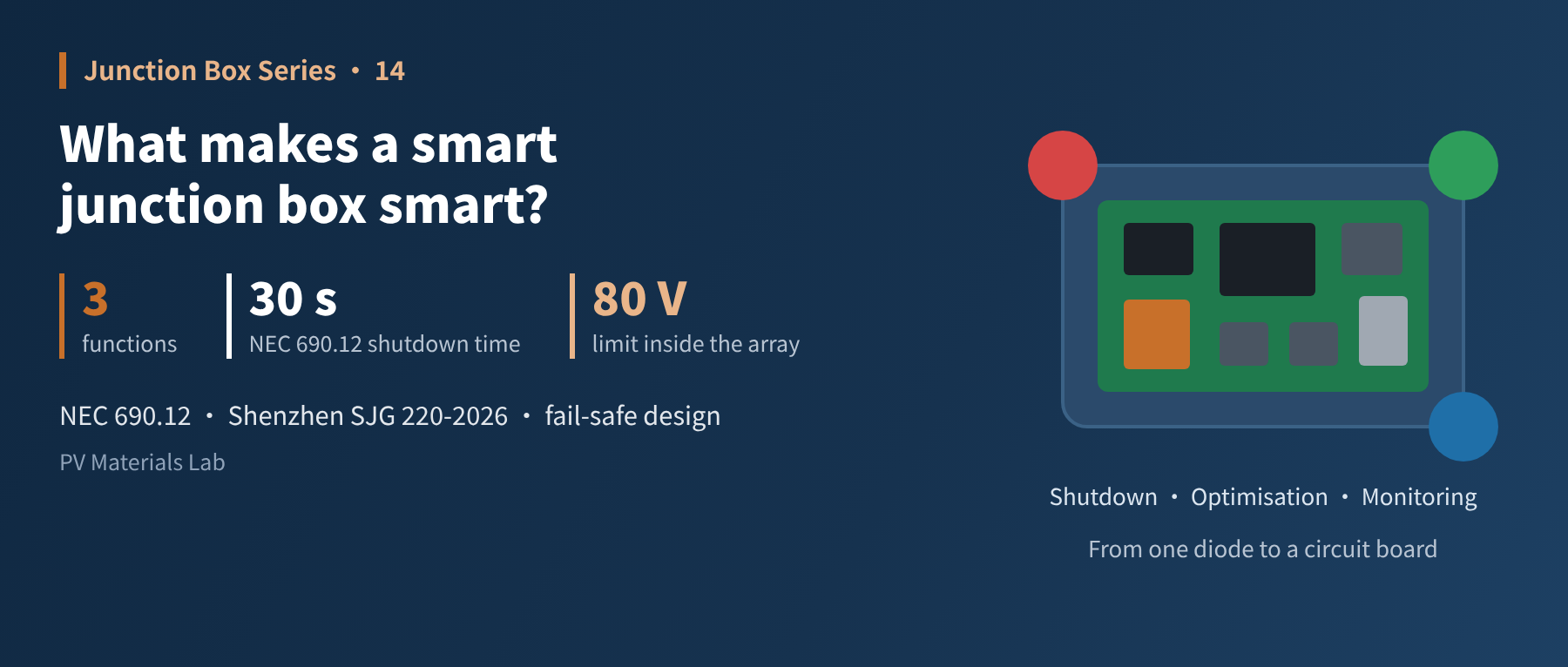
In brief
A standard junction box holds a diode; a smart one holds a circuit board. What the extra functions solve, and what new problems they bring. This is the fourteenth article in our junction box series (Market and Trends: smart versus standard junction boxes).
The conclusion of the last article was that within the existing technical framework, there is little room left to cut junction box costs, and the way forward lies in upgrading the product. The upgrade most talked about in the industry is the smart junction box.
But "smart" is a catch-all. Products that can only shut down remotely, products that optimise output, and products that only collect data are all called smart junction boxes.
This article unpacks the label: which functions "smart" actually means, what problem each solves, and what each costs.
01First, what a standard junction box cannot do
The first thirteen articles were all about standard junction boxes. A standard box is a passive device: there is no powered circuit inside, and whether the diodes conduct is decided entirely by the module's own voltage, with no one giving instructions.
This design is simple, reliable and cheap, but it means there are three things it cannot do:
- It cannot switch off: as long as there is light, the module has voltage. After the inverter shuts down, the DC wiring on the roof still carries hundreds of volts.
- It cannot adjust: every module in a string must carry the same current. When one module is shaded, the diode can only bypass it; there is no finer option.
- It cannot see: the inverter knows only the voltage and current of the whole string, with no way of telling which module has a problem.
The three functions of a smart junction box map one-to-one onto these three "cannots".
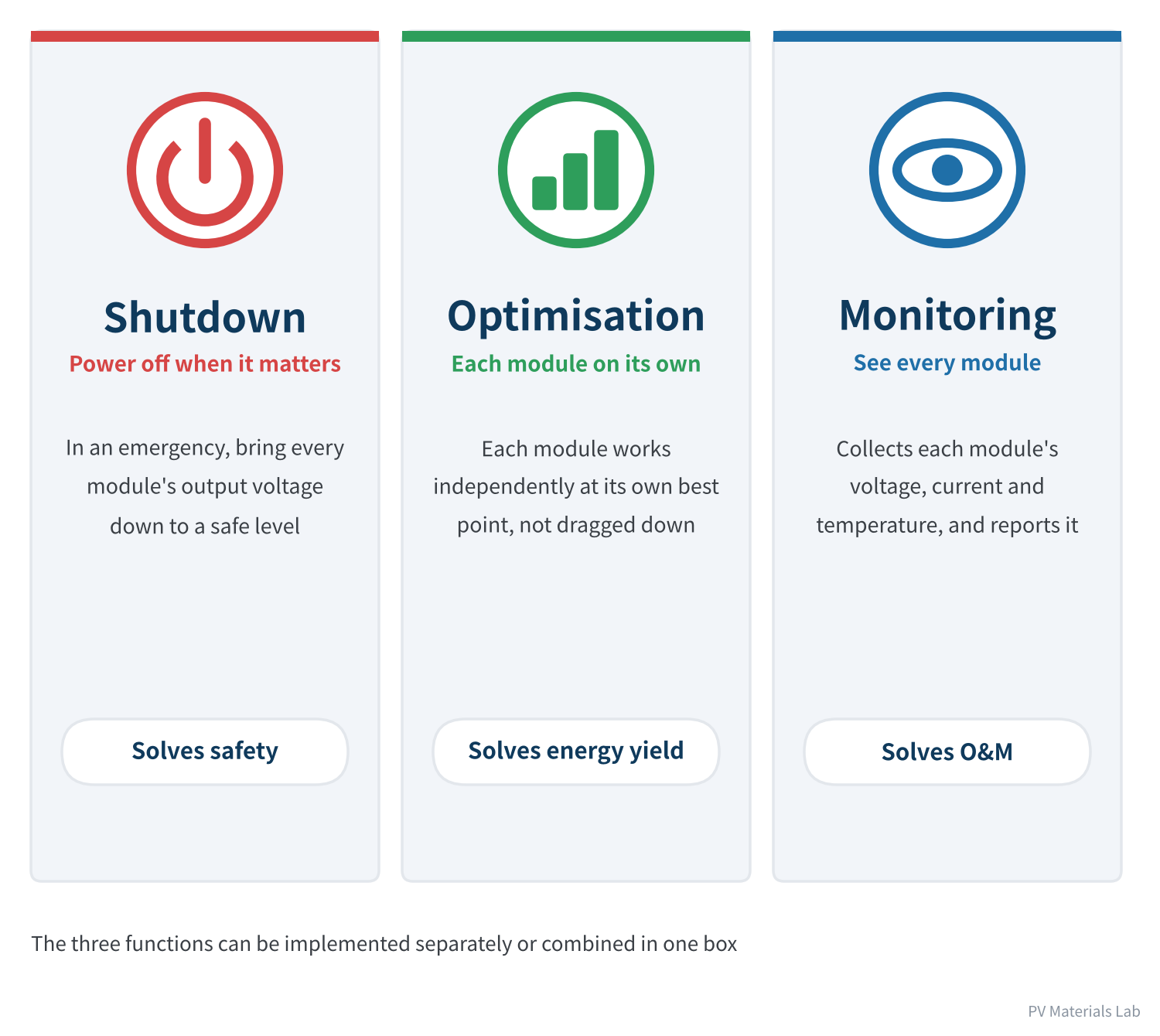
Figure 1 The three functions of a smart junction box
02Function one: shutdown
Shutdown solves a very concrete problem: when a roof is on fire, can firefighters go up there?
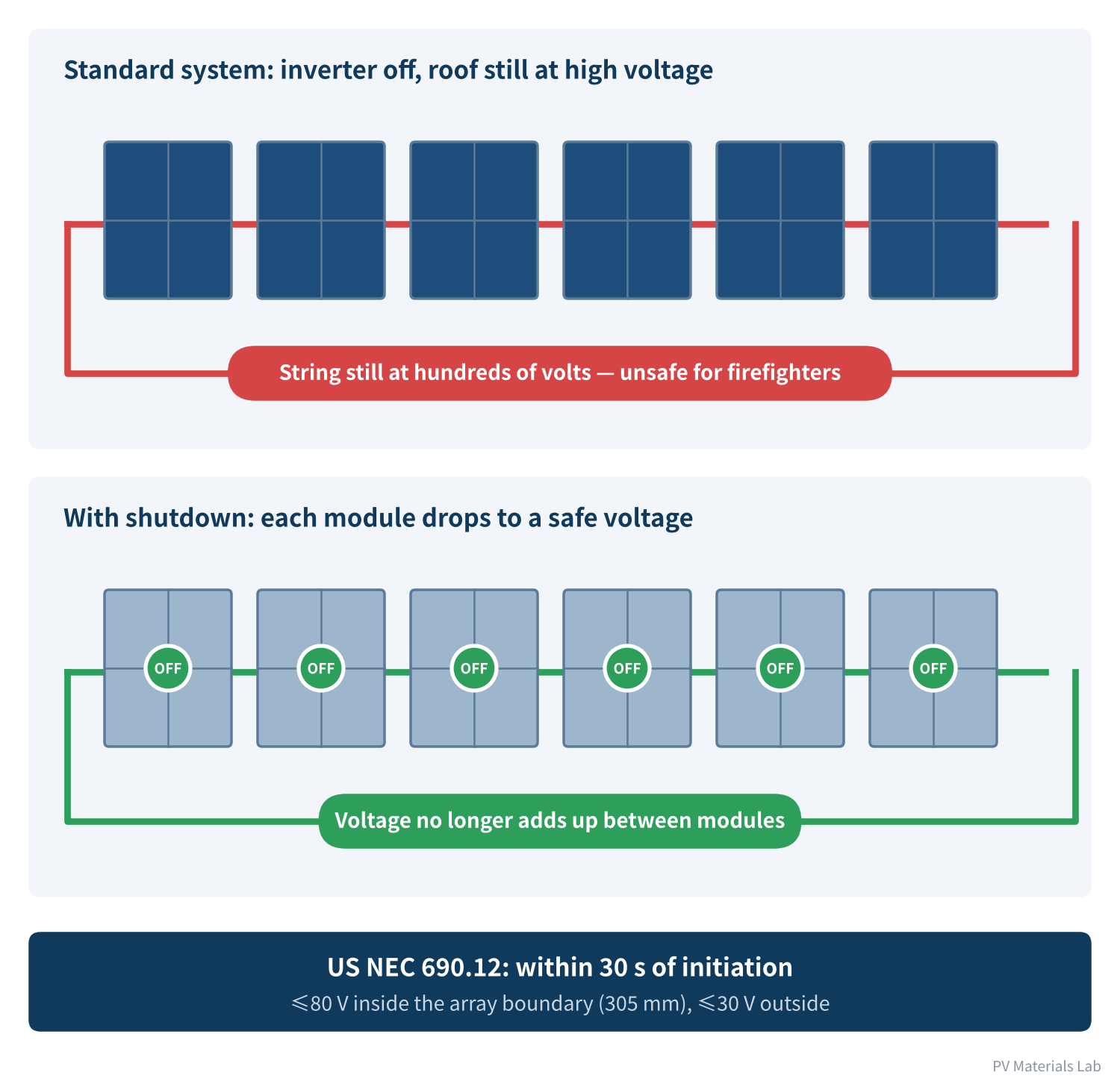
Figure 2 Rapid shutdown: breaking up the high voltage on the roof
The DC side of a PV system has a peculiarity: the power source cannot be switched off. Disconnecting the inverter only cuts its output; modules in sunlight keep generating, and in series their voltage can reach several hundred or even over a thousand volts. When a building is on fire, firefighters spraying water or breaking through the roof may come into contact with these live conductors.
The idea of module-level shutdown is to put a switch on each module that opens on command (or when a "keep-alive" signal is lost), isolating each module so that voltages no longer add up.
Codes are the main driver
The spread of shutdown has been driven mainly by codes. Leading the way is the US National Electrical Code (NEC), whose section 690.12 sets rapid shutdown requirements for PV systems on buildings:
| NEC edition | Requirement |
|---|---|
| 2014 | Rapid shutdown introduced for the first time, covering conductors outside the array |
| 2017 | Defines the "array boundary" as 305 mm (1 ft) from the array; outside the boundary, ≤30 V within 30 s; inside, ≤80 V within 30 s, effective from 1 January 2019 |
| 2020, 2023 | Values carried over; adds compliance routes such as hazard control systems certified to UL 3741 |
| 2026 | Core values unchanged; mainly a reorganisation: explicitly allows emergency stop switches as initiation devices, and requires initiation devices for one- and two-family dwellings to be outdoors. According to industry summaries, no state had adopted the 2026 edition as of May 2026 |
Table 1 Evolution of US NEC 690.12 rapid shutdown requirements
"≤80 V inside the boundary" is the key line. A string's voltage is far above 80 V, so meeting it effectively means shutting down at module level (or using a system-level solution certified to UL 3741). This directly created the product category of module-level rapid shutdown devices.
China: local standards first
The situation in China is different. In 2021 the National Energy Administration issued a draft Notice on Strengthening the Safety of Distributed PV Power Generation, which said PV modules should have a safety shutdown function. From the public information we could find, no national mandatory requirement has yet taken effect, but local standards are starting to follow:
- Beijing: the Technical Specification for Electrical Safety of Distributed PV Systems, in force from 1 April 2023, says systems "should preferably" have rapid shutdown: within 30 s of initiation, the voltage within 305 mm of the array edge must drop below 120 V. This is a recommendation.
- Shenzhen: the local engineering standard SJG 220-2026, Technical Standard for Building-Integrated Photovoltaics, in force from 1 May 2026, says in clause 4.5.19 that PV systems "shall" have rapid shutdown on the DC side close to the modules: within 30 s, voltage within 1 m of the array must drop below 80 V, and below 30 V beyond 1 m; in buildings with automatic fire alarm systems, the shutdown device shall be linked to them. The values are broadly aligned with the NEC.
Practice still varies by region and project type, but the direction is fairly clear: for distributed PV on buildings, rapid shutdown is moving from "recommended" to "required".
03Function two: optimisation
Optimisation tackles the "weakest link" effect: stopping one module's problem from becoming a loss for the whole string.
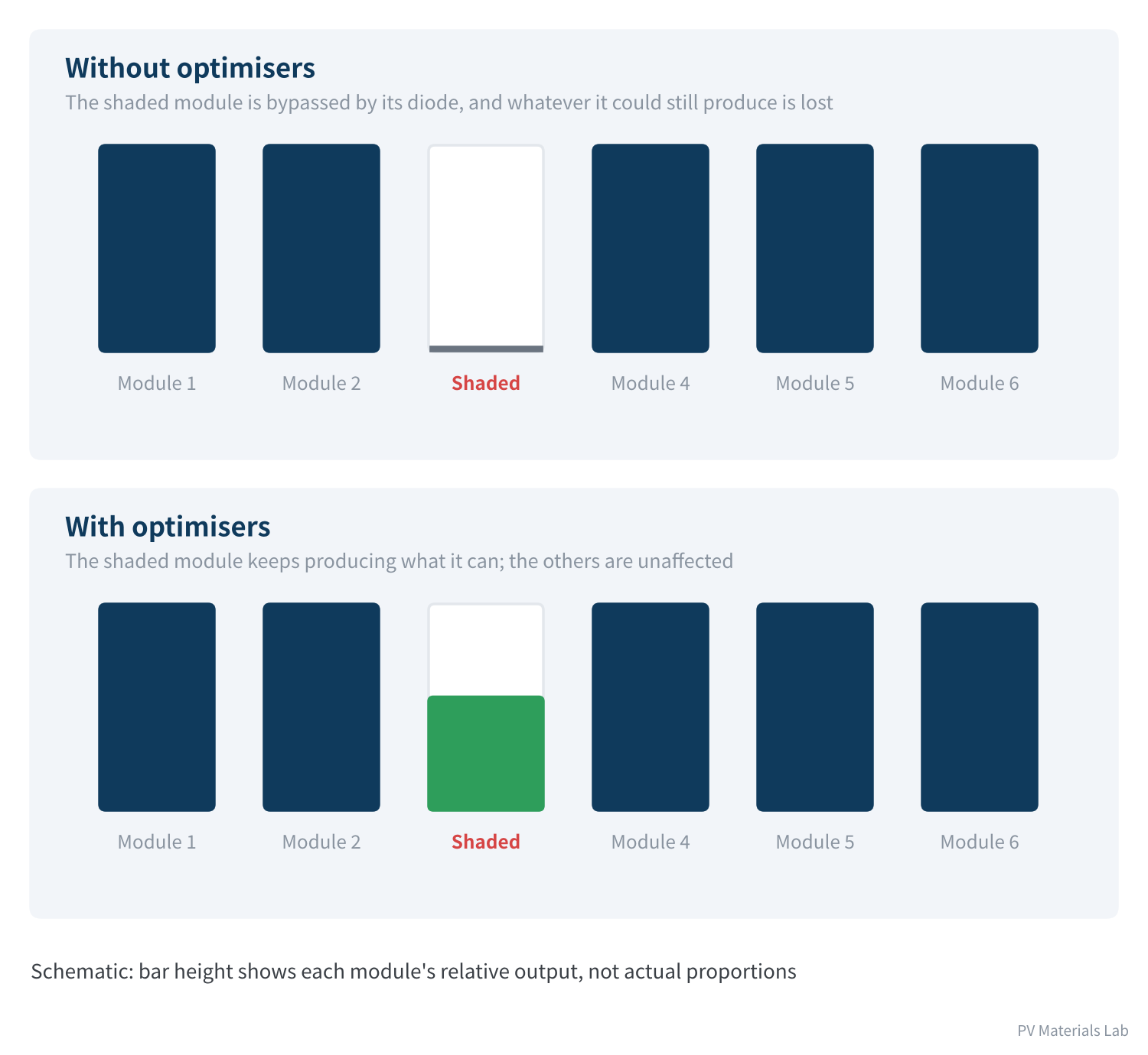
Figure 3 Optimisation: letting each module produce on its own
Article 1 explained how bypass diodes work: when part of the cells is shaded, the diode conducts and current flows around it. This preserves the string current, but at the cost of the shaded part producing nothing — even if it could still produce half its power.
An optimiser is more refined. It is a small DC-DC converter that performs maximum power point tracking for each module individually, "translating" the module's voltage and current into values that suit the series string. Each module can then work at its own best operating point: the shaded one keeps contributing what it can, and the others are unaffected.
When it helps
The value of an optimiser depends entirely on how much modules differ from one another:
- Partial shading: chimneys, parapets or neighbouring buildings shading the roof;
- Mixed orientation: one string spread across roof planes with different orientations or tilts;
- Ageing mismatch: modules mismatched through different degrees of ageing or soiling.
Conversely, in a flat, open, unshaded ground-mounted plant with uniform orientation, modules barely differ, an optimiser recovers very little, and its own conversion has losses. Installing optimisers there is paying for a function you will not use.
04Function three: monitoring
Monitoring is relatively simple: add sensing and communication circuits to the box and transmit each module's voltage, current and temperature.
It does not directly raise energy yield or safety; its value lies in O&M:
- Fast localisation: an underperforming module is obvious at a glance, with no need to check modules one by one;
- Early warning: problems from article 11 such as diode shorts and overheating boxes can be spotted early in the data;
- Fewer roof visits: for numerous, scattered residential and commercial rooftops, the number of roof inspections can be cut sharply.
There are two main communication methods: power-line communication over the DC cables themselves, and wireless. The former needs no extra wiring; the latter is immune to line interference. Each has its uses.
05Two product forms
These functions come in two product forms:
| Item | Integrated (smart junction box) | Add-on (separate optimiser or shutdown device) |
|---|---|---|
| Form | Circuit built into the junction box | Separate box connected to a standard junction box's cables |
| Installation | Fitted at the module factory | Installed module by module on site |
| Connection points | Fewer | Two extra pairs of connectors per module |
| After a failure | Usually the whole module is replaced | Can be replaced on its own |
| Flexibility | Fixed at the factory | Can be added as needed |
Table 2 Integrated versus add-on
The integrated form saves on-site installation and extra connectors — as article 4 explained, every extra pair of connectors is another potential failure point, and the field inspection data cited in article 11 show how common connector problems are. But it ties the life of the electronics to the module: if the circuit fails, the module has to be replaced. The add-on form is the reverse. Both forms coexist on the market today.
06The cost: a circuit board inside the box
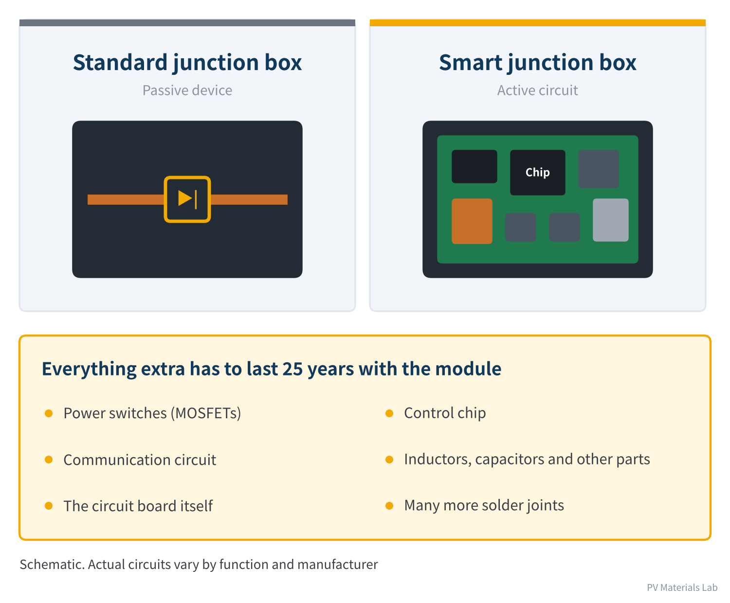
Figure 4 From one diode to a circuit board
From a reliability standpoint, a smart junction box is not "a standard junction box with extra functions" but a different species.
A standard junction box contains only diodes. As article 3 explained, just making that one kind of device work reliably at high temperature for 25 years already takes careful thermal design. A smart junction box contains a whole circuit board: power switches, a control chip, a communication circuit, inductors and capacitors, plus dozens of solder joints connecting them.
Put them back into the five stresses of article 10:
- Temperature: the back of a module can reach 70–80 °C in summer, and the inside of the box more. Electronic component life is very sensitive to temperature, capacitors especially.
- Thermal cycling: every solder joint on the board goes through the daily expansion and contraction calculated in article 10.
- Damp heat: a circuit board is more sensitive to moisture than a diode, demanding more of potting and sealing.
- Self-heating: power circuits have losses when operating, and that heat must also leave the box.
Consumer electronics are typically designed for a few years, industrial electronics for about ten, and modules for 25 years or more. Making electronics last that long is the real technical barrier for smart junction boxes.
When evaluating a smart junction box, beyond its functions, ask: if the circuit inside fails, what happens to the module? The ideal design is fail-safe: if the circuit breaks, the module can at least keep generating normally as if it had a standard junction box, rather than stopping altogether.
Two more costs
- Price: as calculated in article 13, a standard junction box sells for a little over RMB 10 per set. A smart junction box adds a whole electronic circuit, putting its cost in a different league. Whether that money can be earned back through extra generation or compliance needs is a sum every project has to do.
- Certification: beyond the junction box's own standards, products with shutdown must meet rapid-shutdown certification requirements (in North America, for example, rapid shutdown equipment requirements under UL 1741, and UL 3741), and products with power conversion also face electromagnetic compatibility and other requirements. Certification is markedly more complex than for a standard box.
07Which box for which application
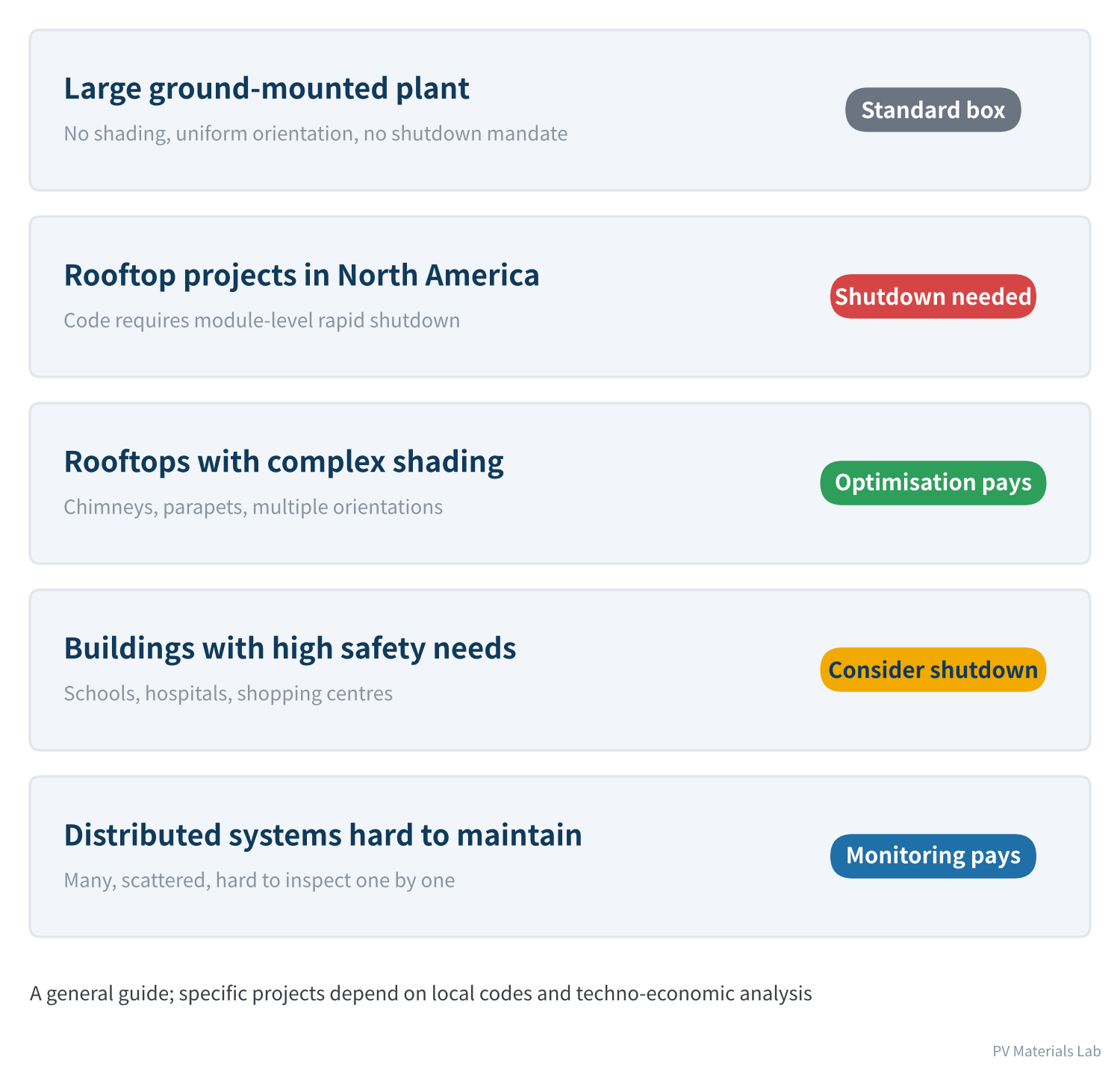
Figure 5 Which box for which application
Pulling it together, the selection logic is quite simple and comes down to three questions:
- Is there a code requirement? If so, there is no choice. Rooftop projects in North America fall here; in China, building-integrated PV projects in Shenzhen now do too.
- Do modules differ much? Only on roofs with complex shading or mixed orientation does optimisation add value.
- Can the extra spend be earned back? Weigh the extra energy and O&M savings against the added investment and potential failure risk.
For large ground-mounted plants, the answer to all three is usually "no", so standard junction boxes will remain the overwhelming mainstream for the foreseeable future. The market for smart junction boxes is in distributed PV, especially in regions with mandatory shutdown requirements.
08From the companies' point of view
Back to the financial reports in article 12. With standard junction box gross margins below 7%, the appeal of smart junction boxes to companies is easy to understand: higher unit prices and higher technical barriers make them less prone to pure price competition. Zeron's annual report divides its products into general-purpose and smart junction boxes, the latter containing chips and offering optimisation, rapid shutdown and monitoring.
But this road is not smooth either. Competitors are no longer just other junction box makers but also power electronics companies specialising in optimisers, shutdown devices and microinverters; the main markets are overseas and heavily affected by local codes and trade conditions; and the capabilities required — circuit design, chips, software, communications — are a different skill set from the moulding, stamping and assembly that traditional junction box makers excel at.
So it is more accurate to say that smart junction boxes are a niche market with barriers to entry, not a natural upgrade of the standard junction box.
09Final thoughts
1. A standard junction box is a passive device: it cannot switch off, adjust or see.
2. The three functions of a smart junction box: shutdown addresses safety, optimisation addresses mismatch losses, and monitoring addresses O&M.
3. Shutdown is driven mainly by codes, typified by the module-level requirement of US NEC 690.12; in China, Shenzhen's SJG 220-2026 has introduced a broadly aligned mandatory requirement.
4. The value of optimisation depends on how much modules differ, and is small in unshaded ground-mounted plants.
5. The core challenge of smart junction boxes is making electronics work on the back of a module for 25 years, with fail-safe behaviour.
6. It is a niche market with barriers to entry, centred on distributed PV and regions with mandatory requirements.
Intelligence is only one direction in which junction boxes are evolving. Higher voltages, larger currents, new cell technologies and module structures all place new demands on the junction box. We will cover these together in the next article.
In the next article, Junction Box Series 15 looks at future directions: higher system voltages, larger currents, BC and tandem cells, lightweight flexible modules, and how junction boxes need to keep up.
Have you used smart junction boxes or module-level shutdown in your projects? How did they perform, and what problems came up? We would be glad to hear from you.
References
- US National Electrical Code (NFPA 70) 690.12, Rapid shutdown of PV systems on buildings
- UL 3741, Photovoltaic hazard control
- China National Energy Administration: Notice on Strengthening the Safety of Distributed PV Power Generation (draft for comment), November 2021 (in Chinese)
- Beijing: Technical Specification for Electrical Safety of Distributed PV Systems, in force 1 April 2023 (as interpreted by APsystems, in Chinese), https://www.apsystems.cn/news/322.html
- Shenzhen SJG 220-2026, Technical Standard for Building-Integrated Photovoltaics, in force 1 May 2026 (in Chinese), https://zjj.sz.gov.cn/attachment/1/1692/1692731/12686461.pdf
- SurgePV: NEC 2026 rapid shutdown changes (May 2026), https://www.surgepv.com/blog/nec-2026-rapid-shutdown-solar
- Jiangsu Zeron New Energy Technology Co., Ltd.: 2025 annual report summary (in Chinese)
- IEC 62790:2020 Junction boxes for photovoltaic modules – Safety requirements and tests
A PV R&D and technology team with 10+ years of experience | In-depth technical knowledge sharing
Materials · Reliability · Failure Analysis · Standards & Certification · Products · Processes
Exploring AI + PV; collaboration welcome
Disclaimer:
1. Original content reflects the authors' personal views only, is for reference only and does not constitute investment advice.
2. Reposted and cited content is credited to its source, out of respect for original work.
3. Some content was produced with AI assistance (chart generation, data retrieval, concept explanations, etc.); the core framework and key content were written by our technical team and reviewed by people.
4. If anything is inaccurate or infringes your rights, please leave a message or contact us and we will deal with it.