
Junction Box Series 15 | 2000 V, Higher Currents, Tandem Cells: Where Do Junction Boxes Go Next?
In brief
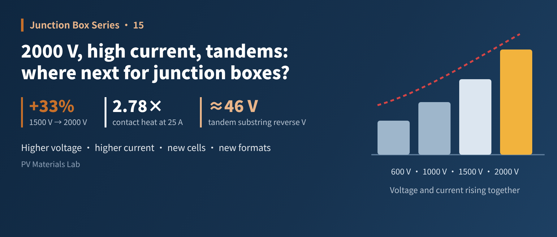
Of the five forces reshaping junction boxes, four come from modules and systems. What higher voltage, higher current, new cells and new module formats each ask of the junction box. This is the fifteenth article in our junction box series (Market and Trends: future directions).
The last article covered smart junction boxes. They are one direction in which junction boxes are evolving, but not the only one, and not even the one with the widest impact.
The junction box is a supporting component of the module. Where it goes is largely not its own decision but set by the technology roadmap of modules and systems: when system voltage rises, it must follow; when cell current grows, it must follow; when cells change technology or modules change format, it must follow again.
This article lays out these "upstream changes" one by one and looks at what problem each sets for the junction box, and which answers already exist.
This article is about trends. Some are already happening and some are at an early stage. Wherever forecasts or technologies not yet in mass production are involved, we say so. Our view of trends is our own opinion, for reference only.
01Five forces
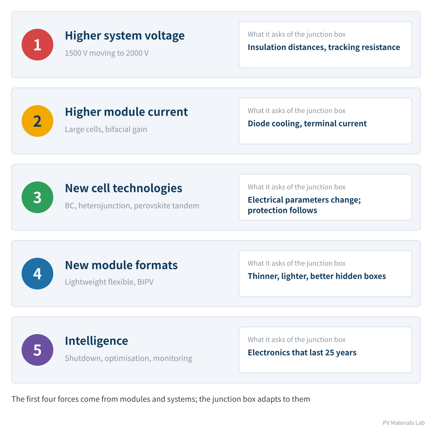
Figure 1 Five forces driving change in junction boxes
Of the five, the fifth, "intelligence", was covered in the last article. This article covers the first four.
02Higher system voltage: from 1500 V to 2000 V
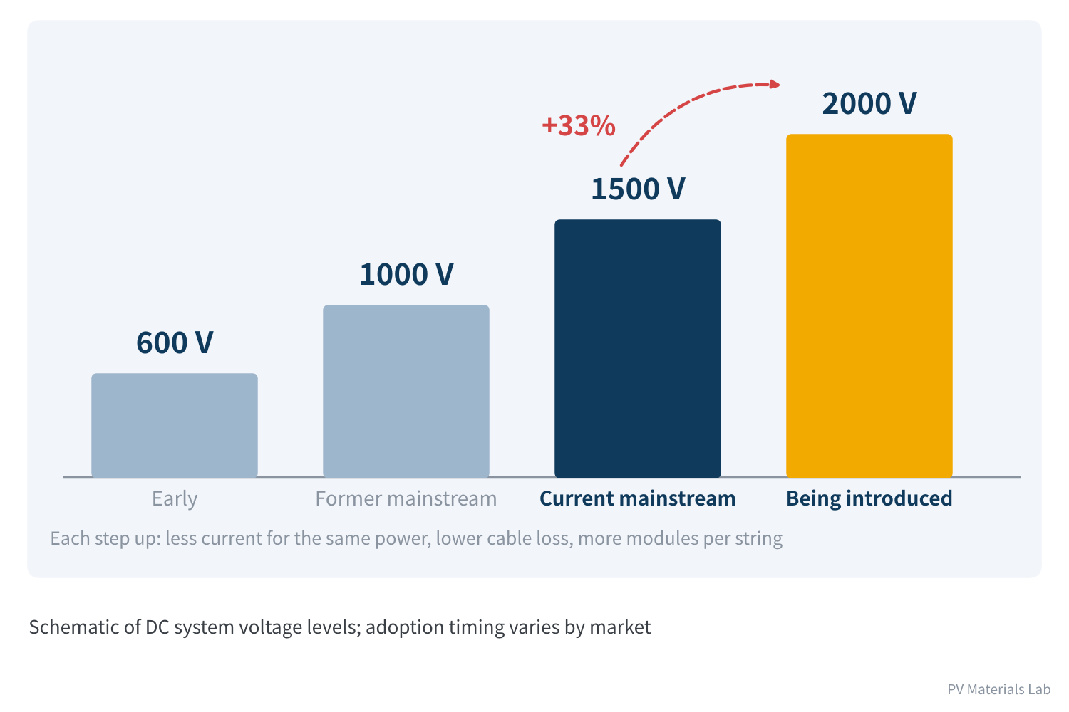
Figure 2 Four steps of system voltage
The DC system voltage of PV plants has been rising steadily. The reason is simple: power equals voltage times current, so for the same power, higher voltage means lower current and lower cable losses; more modules fit in each string, and combiner boxes, cables and structures are all reduced.
From 1500 V to 2000 V is a 33% increase. This step is no longer just a concept: certification requirements for 2000 V junction boxes and connectors were published in 2023, a module maker obtained 2000 V module certification in 2024 (UL Solutions issued the world's first UL 61730 2000 V certificate to JinkoSolar), and test sites and demonstration projects have followed. The prevailing industry view is that large-scale adoption is still two to three years away.
What it means for the junction box
Higher voltage concentrates the requirements on insulation, in three specific ways:
- Larger creepage distances and clearances: distances between live parts, and from live parts to external surfaces, must be redesigned for the higher voltage. And the requirement does not grow proportionally: the higher the voltage, the more concentrated the electric field, and the faster the needed margin increases.
- Higher tracking resistance of materials: article 2 introduced CTI: the higher it is, the shorter the creepage distance needed at the same voltage. Where box size is constrained, materials with a higher CTI class are one of the main ways to meet 2000 V requirements.
- "Taking the long way round" in the structure: adding ribs and barriers between terminals lengthens the surface path, gaining creepage distance without enlarging the box.
Connectors and cables follow the same logic: thicker insulation, longer creepage paths when mated. 2000 V junction boxes, connectors and cables are a new set of ratings and must not be mixed with 1500 V products. The cross-mating risk discussed in article 4 only gets worse when voltage classes are mixed.
03Higher module current
As article 1 explained, module operating current has risen from about 9 A in the early days to 14–18 A or more, and junction box current ratings have climbed from 15 A to 25 A and 30 A. The trend continues: cell efficiency is rising and bifacial rear-side gain adds on top. As calculated in article 9, under the BSI condition of IEC 61215:2021 the diode test current for bifacial modules must also include rear-side gain.
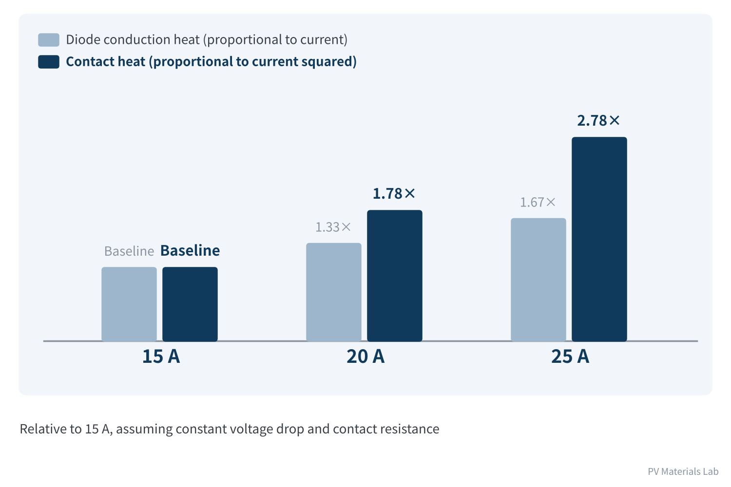
Figure 3 As current rises, heat rises faster
Current affects the junction box in two ways that scale differently:
- Diode conduction heat is roughly proportional to current: from 15 A to 25 A, heat becomes 1.67 times.
- Heat at contacts and conductors is proportional to the square of current: from 15 A to 25 A, heat becomes 2.78 times.
So as current grows, the pressure on "resistive" links — solder joints, terminals, connectors — grows even faster than on the diodes. The three responses from article 3 — better Schottky diodes, stronger heat dissipation and low-loss MOSFET solutions — all become more necessary at high current.
There is an easily overlooked link here: raising system voltage to 2000 V is meant to increase string power without increasing current. But the module's own current is set by its cells and does not fall because system voltage rises. So the junction box faces voltage and current rising together, and both insulation and heat dissipation must be strengthened.
04New cell technologies
BC and heterojunction: little change, details to adjust
Back-contact (BC) cells put both positive and negative electrodes on the back of the cell, and heterojunction cells differ from the mainstream in process temperature and encapsulation. Their demands on the junction box show up mainly in module layout and how ribbons are brought out; the principle and structure of the junction box itself do not change fundamentally.
What deserves attention is the difference in electrical parameters. Cells of different technologies differ in open-circuit voltage, short-circuit current and reverse breakdown behaviour, which affects diode selection and hot-spot protection design. With a change of cell technology, the diode thermal test and hot-spot test in module certification discussed in article 9 must be repeated.
Perovskite tandems: protection may need rethinking
Perovskite-silicon tandem cells are the most closely watched next-generation technology. They are not yet in mass production, but they have left the lab: according to TaiyangNews coverage of an industry conference in May 2026, JinkoSolar has a certified tandem cell efficiency of about 34.7% with an open-circuit voltage of about 2.0 V; GCL has reached 27.06% on a near-commercial 1.71 m² module and runs a 500 MW production line; the first commercial tandem modules are on sale, though GW-scale production is still unproven. Their electrical characteristics differ greatly from today's silicon cells and are worth thinking about in advance.
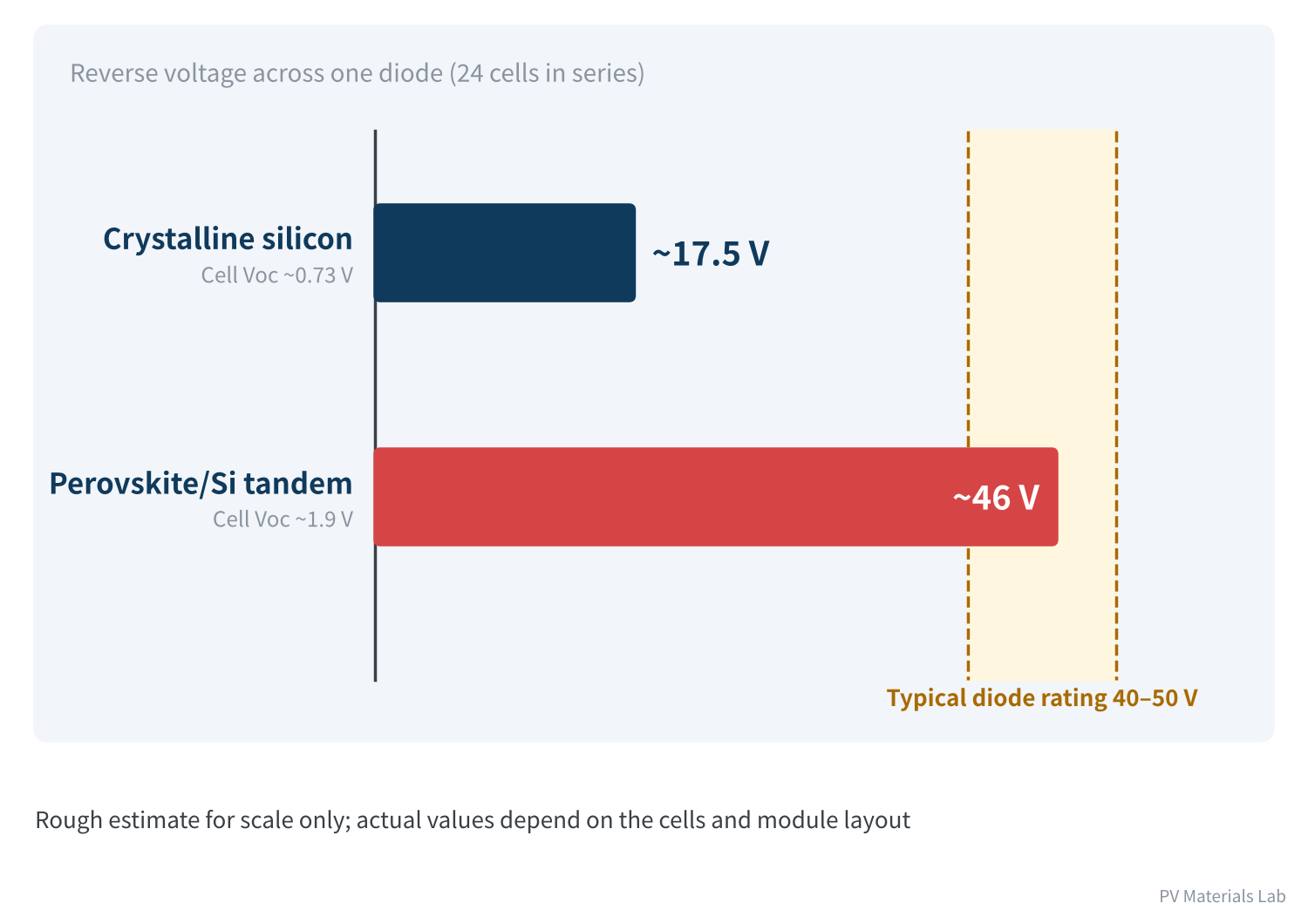
Figure 4 Tandem cells: higher voltage — is the diode rating still enough?
As calculated in article 2, the reverse voltage across a diode roughly equals the open-circuit voltage of the substring it protects.
A silicon cell has an open-circuit voltage of about 0.73 V; 24 in series give about 17.5 V, and common 40–50 V diodes have ample margin.
A two-terminal tandem cell has two sub-cells in series, with a cell open-circuit voltage of around 1.9 V (the latest certified results reach about 2.0 V). With the same 24 cells in series, that is about 46 V, or about 48 V at 2.0 V.
That is already at the top of the common diode rating range, with almost no margin left.
The implication: if tandem modules keep today's layouts and diodes, the voltage rating may not be enough. There are two ways out — diodes with a higher voltage rating, or fewer cells per diode, meaning more diodes.
On the other hand, tandem cells carry much less current than silicon cells of the same size, so the heat burden when the diode conducts actually eases. With voltage up and current down, the design focus of the junction box has to shift accordingly.
There is also a deeper issue: research shows that perovskite materials are far more sensitive to reverse bias than silicon, and more prone to irreversible damage under the reverse bias caused by partial shading. This means the protection logic from article 1 — "the bypass diode caps the hot spot" — may not be enough for perovskites, and finer protection may be needed. Both academia and industry are working on this, and there is no settled answer yet.
05New module formats
- Lightweight and flexible modules: used on roofs with limited load capacity, curved surfaces and mobile applications. With no glass and no aluminium frame, conventional junction boxes look large and heavy by comparison. The requirements are thinner, lighter boxes that can bond to flexible substrates — the bonding process from article 6 faces completely different materials here.
- Building-integrated modules: PV becomes part of the roof or façade. The junction box needs to be hidden, commonly as a flat edge-mounted box or integrated into frames and profiles. Buildings also demand more of fire safety, and BIPV standards such as Shenzhen's SJG 220-2026 add rapid shutdown requirements (see the last article).
- Bifacial glass-glass modules: already mainstream. The junction box should be as small and as close to the edge as possible to minimise rear-side shading, which is one reason split junction boxes have spread.
What these applications share: they constrain the shape of the box, and shape is exactly what determines heat dissipation and insulation distances. The thinner and smaller the box, the harder it is to handle "heat as the main thread" from article 2.
06Two paths of evolution
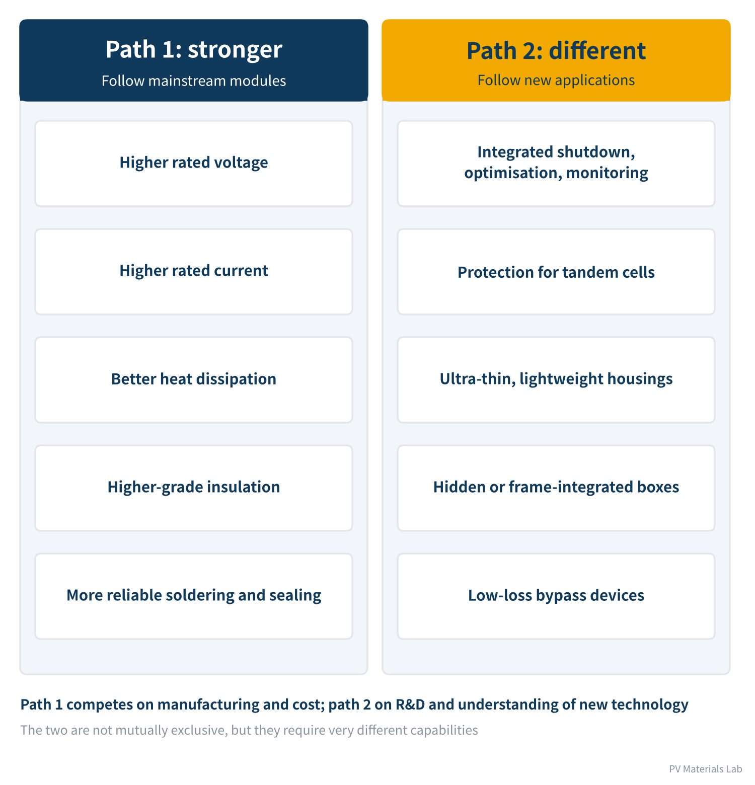
Figure 5 Two paths of junction box evolution
Pulling it together, junction box evolution broadly follows two paths:
- Path 1, stronger: follow mainstream modules, raising voltage and current ratings, heat dissipation and insulation step by step. This is the existing market, the largest by volume, where competition is on manufacturing capability and cost control.
- Path 2, different: follow new applications — intelligence, protection for tandem cells, ultra-thin and hidden housings. This is the incremental market, still small, where competition is on R&D capability and understanding of new technology.
Read alongside the financial reports in article 12, the market for path 1 already runs at gross margins below 7% and faces pressure from module makers' in-house production; article 13 showed that 2026 copper prices have added further cost pressure. That explains why the listed companies are all investing in path 2, or moving beyond junction boxes into other businesses altogether.
What does not change
Technology roadmaps change, but some things do not. Looking back over the whole series, the junction box's three main functions — current extraction, bypass protection, sealing and insulation — remain in every new technology, and so does the thread running through it all: heat dissipation.
New technologies change parameters and constraints, not the laws of physics. Higher voltage means managing insulation, higher current means managing heat, and a smaller box makes both harder. Understand these basic relationships, and you can judge what problems any new module technology will bring to the junction box.
07Final thoughts
1. Junction box evolution is driven mainly by the technology roadmap of modules and systems.
2. 2000 V has moved from concept to certification and demonstration; its core demands on the junction box are insulation distances and the tracking resistance of materials.
3. As current increases, heat at contacts and conductors grows with the square of current, putting more pressure on them than on the diodes.
4. BC and heterojunction bring little change; perovskite tandems have high voltage, low current and sensitivity to reverse bias, are entering small-scale commercial use, and may require protection to be redesigned.
5. Lightweight flexible modules and BIPV require thinner, smaller boxes, in tension with heat dissipation and insulation.
6. Two paths: "stronger" competes on manufacturing, "different" on R&D.
That covers every aspect of the junction box, from function, structure, manufacturing, testing, certification and reliability to market and trends. The final article moves to the buyer's side: with all this knowledge in hand, what should you actually look at when selecting products and auditing factories?
In the next article, Junction Box Series 16 takes the buyer's perspective on selection and factory audits, turning the first fifteen articles into a checklist you can use directly.
Which do you think will change junction boxes substantively first: 2000 V or tandem cells? We would be glad to hear from you.
References
- OFweek Solar: "The 2000 V era is coming — are your modules and cells ready?", August 2026 (in Chinese)
- UL Solutions: market access services for PV products for 2000 Vdc systems; world's first UL 61730 2000 V certificate (JinkoSolar) (in Chinese), https://www.ulsolutions.com.cn/news/customer-events/quanqiushouzhangul-solutionsweijingkenengyuanbanfaul-61730-2000vrenzhengzhengshu
- E. J. Wolf et al., Designing Modules to Prevent Reverse Bias Degradation in Perovskite Solar Cells when Partial Shading Occurs, Solar RRL, 2022
- TaiyangNews: Beyond Silicon Limits: TaiyangNews Conference Maps Commercialization Path For Perovskite Tandems (2026-05-12), https://taiyangnews.info/amp/story/technology/beyond-silicon-limits-taiyangnews-conference-maps-commercialization-path-for-perovskite-tandems
- IEC 62790:2020 Junction boxes for photovoltaic modules – Safety requirements and tests
- IEC 61215:2021 Terrestrial photovoltaic (PV) modules – Design qualification and type approval
A PV R&D and technology team with 10+ years of experience | In-depth technical knowledge sharing
Materials · Reliability · Failure Analysis · Standards & Certification · Products · Processes
Exploring AI + PV; collaboration welcome
Disclaimer:
1. Original content reflects the authors' personal views only, is for reference only and does not constitute investment advice.
2. Reposted and cited content is credited to its source, out of respect for original work.
3. Some content was produced with AI assistance (chart generation, data retrieval, concept explanations, etc.); the core framework and key content were written by our technical team and reviewed by people.
4. If anything is inaccurate or infringes your rights, please leave a message or contact us and we will deal with it.