
From PERC to TOPCon, HJT, BC and 0BB: New Tests That Cell Technology Sets for Soldering Flux
In brief
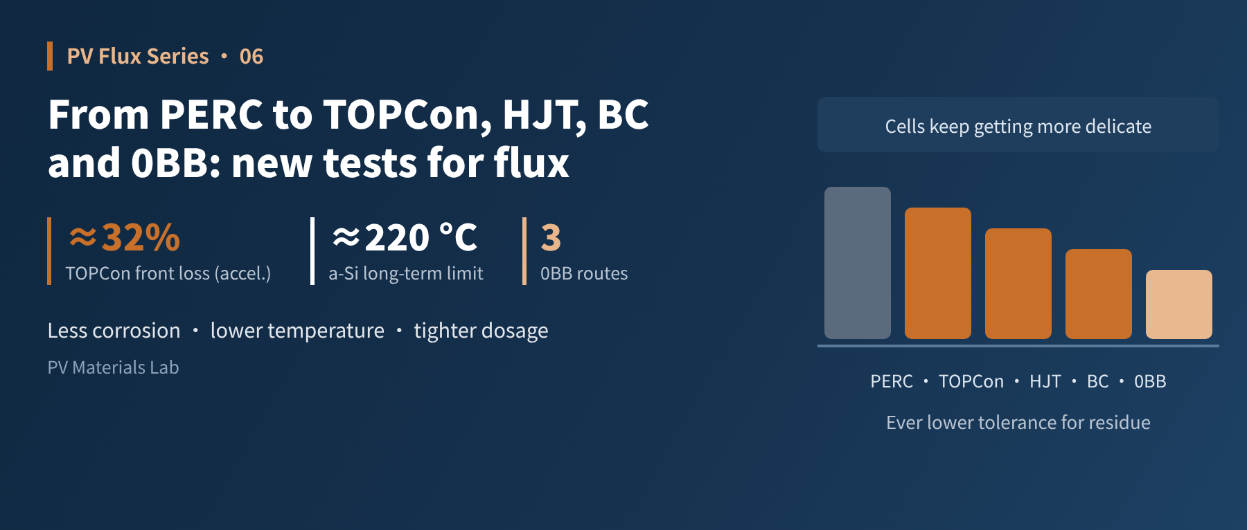
In the PERC era, flux that could "make the joint" was largely good enough. With TOPCon, HJT, BC and 0BB, what is soldered, how much heat cells tolerate and how they are interconnected are all changing, and the tests for flux keep getting harder. This article works through them: why TOPCon's front Ag-Al contacts have become a corrosion weak spot, why HJT faces the twin constraints of ITO corrosion and low-temperature soldering, how fine fingers, multi-busbar and fine round wire ribbon make dosage control ever more precise, and whether flux "stays" or "exits" in the various BC and 0BB interconnection routes. This is the sixth article in our PV soldering flux series.
At the end of the last article we noted that low-temperature soldering requires the flux activation window to move down. That is only one of the tests cell technology has set for flux. Over the past few years, cells have moved from PERC to TOPCon, HJT and BC, and interconnection from multi-busbar to 0BB. What gets soldered has changed, heat tolerance has changed, and some routes no longer solder at all. This article looks at the new requirements route by route.
01The changes at a glance
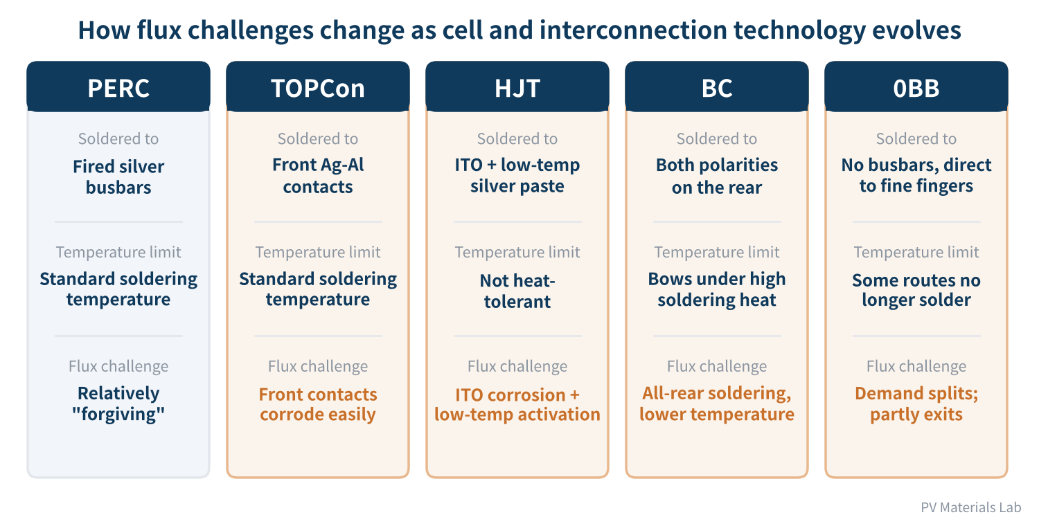
Figure 1 How flux challenges change as cell and interconnection technology evolves
The trend can be summed up in one sentence: cells are becoming more delicate, and the focus for flux is shifting from "makes the joint" to "kind to the cell". In the PERC era, flux was soldered to high-temperature fired silver busbars with relatively stable surfaces; enough activity and controlled residue were generally sufficient. Each technology since has tightened the constraints in some direction.
02TOPCon: the front Ag-Al contact becomes the weak spot
TOPCon cells usually use aluminium-containing silver paste on the front to contact the p+ emitter. A study by the University of New South Wales (UNSW) on several TOPCon cells found that under damp heat, two commercial no-clean fluxes both caused marked corrosion of the front Ag-Al contacts, raising series resistance and lowering efficiency, while the rear silver contacts barely degraded — which the researchers attribute to the greater chemical stability of the rear paste. In the team's conference report, unencapsulated cells sprayed with flux and held at 100 °C/85% RH for 122 hours lost about 32% (relative) of front-side efficiency in the halogen-containing flux group, while no rear-side group changed significantly.
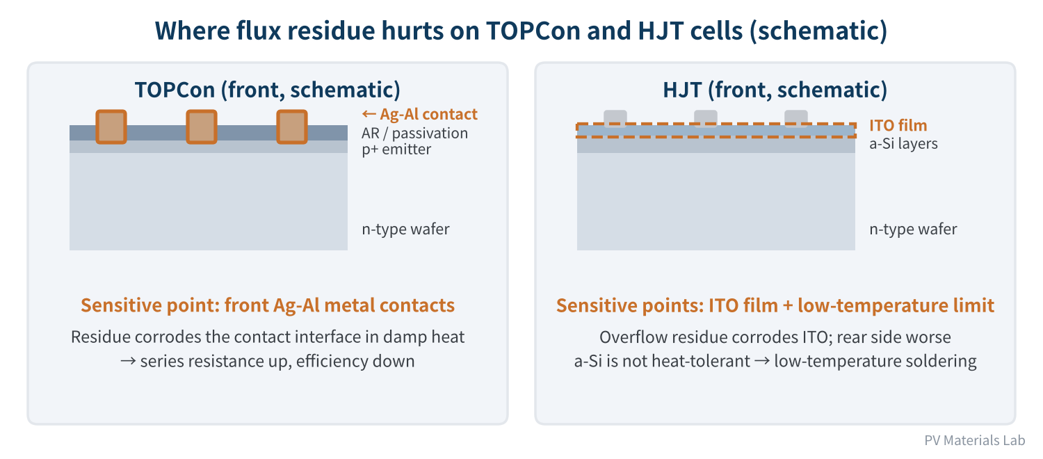
Figure 2 Where flux residue hurts on TOPCon and HJT cells (schematic)
Several details of this research deserve attention:
- Halogens do more damage: the flux with a dicarboxylic acid activator and higher halogen content was markedly more corrosive, but the flux with a malic acid activator and much lower halogen content also caused considerable degradation. "Halogen-free" does not mean "safe".
- Metallisation matters too: denser metallisation and lower aluminium content improve corrosion resistance. In the same study, cells from a 2019 batch barely degraded, while a 2022 batch, whose front contacts were already fairly porous, was clearly affected by flux. The problem is not only on the flux side; cell pastes must be optimised too.
- Screen early: the researchers recommend unencapsulated cell-level damp heat testing before module assembly to identify flux risks quickly, choosing formulations with as little halogen as possible and optimised acid content, and optimising paste composition and structure to limit flux infiltration.
For module makers, this means a flux that works well on PERC may need re-validation on TOPCon; even among TOPCon cells, results can differ between cell makers, paste systems and batches. The team's late-2025 follow-up work also found that laser-assisted firing (LAF) clearly reduces, but does not eliminate, this contact corrosion.
03HJT: two constraints — ITO corrosion and low-temperature soldering
HJT cells set two "gates" for flux.
- Gate one, ITO is vulnerable to corrosion: both sides of an HJT cell are covered with an ITO transparent conductive film. A study by a team at KETI in Korea found that even small amounts of flux residue overflowing onto the ITO markedly reduce its conductivity under damp heat, with the rear ITO more affected (which the researchers link to its greater SnO₂ segregation and more oxygen vacancies); more acidic fluxes caused more degradation. Drying the flux and blowing off the excess before soldering essentially avoided this degradation.
- Gate two, the cell is vulnerable to heat: HJT's amorphous silicon passivation layers are not heat-tolerant; Fraunhofer ISE's research notes they degrade severely when exposed above about 220 °C for longer durations. HJT therefore usually uses low-temperature soldering (for example tin-bismuth solders), or avoids soldering altogether with conductive adhesives. With low-temperature solder, the flux must activate at lower temperatures.
In addition, HJT fingers usually use low-temperature-cured silver or silver-coated copper pastes, whose surfaces differ from fired silver and place different demands on flux wetting. Flux for HJT essentially needs to be "dedicated"; it is hard to carry over PERC or TOPCon formulations and processes directly.
TOPCon must guard against "contact corrosion"; HJT must guard against "ITO corrosion" and work at low temperature. What they share: both tolerate far less flux residue than PERC.
04Fine fingers, multi-busbar and fine round wire ribbon: ever more precise dosage
To cut silver consumption and raise efficiency, fingers keep getting finer, busbars more numerous, and ribbon is moving from flat to fine round wire. These changes place new process demands on flux:
- Smaller contact area: the contact between ribbon and fingers is narrower, demanding faster and more uniform wetting; local underdosing easily causes cold joints.
- Lower tolerance for dosage: the finer the ribbon, the less flux it needs, and "a bit extra" can overflow beyond the joint, creating corrosion risk on TOPCon and HJT.
- Harder positioning: fine round wire ribbon slips and shifts more easily, and excess liquid flux reduces positioning stability. The fine-wire ribbon flux mentioned earlier lists "reduced placement slipping" as one of its main benefits.
05BC and 0BB: flux "exits" or "changes role"
BC and 0BB bring more fundamental change: some routes start to bypass conventional soldering altogether.
- BC cells: BC cells have both polarities on the rear, so all soldering is on one side. According to a TaiyangNews report in February 2026, Sweden's Sticky Solar Power points out that the roughly 240 °C of conventional stringing makes BC cells bow, creating crack and breakage risks. Its tape solution applies no heat and no soldering at the stringing stage: copper wires are held by tape, and electrical interconnection is completed during lamination (maximum about 160 °C).
- 0BB: 0BB removes the busbars, with ribbon contacting the fine fingers directly. According to an SMM industry analysis from early 2025, there are three main 0BB routes: the "soldering + adhesive" route still solders first and then fixes the ribbon, so flux keeps working; the "adhesive dispensing" route holds the ribbon with glue dots and alloys the contact during lamination, eliminating the conventional soldering step; and the "film covering" route laminates film, ribbon and cells into strings in one go, with no flux needed.
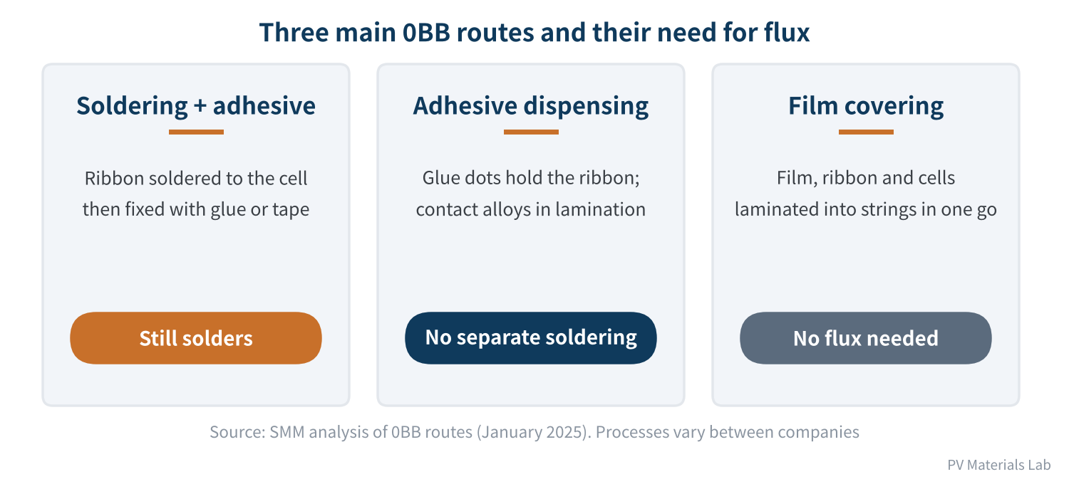
Figure 3 Three main 0BB routes and their need for flux
So to the question "will 0BB make flux obsolete?", the answer is: not entirely, but demand will split. Routes that keep soldering will demand even lower residue, lower corrosivity and more precise dosage from flux; in routes that no longer solder, flux exits — but the job of "removing oxide and ensuring reliable contact" does not disappear; it moves to ribbon coatings, encapsulant films and the lamination process.
Technology change has not made flux less important; it has narrowed where flux is used and raised the bar. The flux that remains must understand cells better.
06Final thoughts
The new tests that cell technology sets for flux come down to three points:
- Less corrosion: TOPCon's Ag-Al contacts and HJT's ITO are both more sensitive to residue; "halogen-free" is no longer sufficient, and acid content and residue amount matter just as much;
- Lower temperature: HJT and BC push soldering temperatures down, and flux activation windows must follow;
- More precise dosage: fine fingers, multi-busbar and fine round wire ribbon lower the tolerance for dosage, and some 0BB and BC routes bypass soldering altogether.
This article kept returning to how residue behaves in damp heat. In fact, residue affects more than the cell: it is sealed in by lamination and stays in long-term contact with EVA and POE encapsulants. The next article opens the reliability part of the series with compatibility between flux and encapsulation materials: how residue can cause yellowing, bubbles and delamination, and how to test and judge it.
When you switched to TOPCon or HJT, did your flux change too? What problems did you run into? We would be glad to hear from you.
References
- pv magazine: UNSW study shows impact of soldering flux on TOPCon solar cell degradation, 2025 (original: Assessing the impact of solder flux-induced corrosion on TOPCon solar cells, Solar Energy Materials and Solar Cells), https://www.pv-magazine-india.com/2025/08/18/unsw-study-shows-impact-of-soldering-flux-on-topcon-solar-cell-degradation
- J. Fu et al.: Assessing Soldering Flux-Induced Corrosion on TOPCon Solar Cells, APVI Solar Research Conference, 2024, https://apvi.org.au/solar-research-conference/wp-content/uploads/2024/12/Fu_J_Assessing_Soldering_Flux-Induced_Corrosion_on_TOPCon_Solar_Cells.pdf
- A. Li et al.: Elucidating the Impact of Soldering Flux-Induced Degradation on the Reliability of TOPCon Solar Cells with and without Laser-Assisted Firing under Damp-Heat Stress, APVI Solar Research Conference, 2025, https://apvi.org.au/solar-research-conference/wp-content/uploads/2025/12/48.pdf
- G. Park et al.: Soldering flux causes corrosion of indium tin oxide electrode in heterojunction solar cells, Cell Reports Physical Science, 2025, https://www.sciencedirect.com/science/article/pii/S2666386425002188
- A. De Rose et al.: Interconnection of Silicon Heterojunction Solar Cells by Infrared Soldering, 36th EU PVSEC, 2019, https://www.ise.fraunhofer.de/content/dam/ise/de/documents/publications/conference-paper/36-eupvsec-2019/DeRose_2CO114.pdf
- TaiyangNews: A New ECA-Based Stringer for HJT from Teamtechnik
- TaiyangNews: Tape-Based Interconnection Approach for BC Modules, 2026-02-25, https://taiyangnews.info/technology/tape-based-interconnection-approach-for-bc-modules
- SMM: [SMM Analysis] 0BB Technology and Cost of Encapsulation Film for Different Routes (Part 1), 2025-01-05, https://news.metal.com/newscontent/103121370/[SMM-Analysis]-0BB-Technology-and-Cost-of-Encapsulation-Film-for-Different-Routes-Part-1
- MacDermid Alpha: ALPHA SF828-MBB PV flux technical data sheets, 2023/2026
A PV R&D and technology team with 10+ years of experience | In-depth technical knowledge sharing
Materials · Reliability · Failure Analysis · Standards & Certification · Products · Processes
Exploring AI + PV; collaboration welcome
Disclaimer:
1. Original content reflects the authors' personal views only, is for reference only and does not constitute investment advice.
2. Reposted and cited content is credited to its source, out of respect for original work.
3. Some content was produced with AI assistance (chart generation, data retrieval, concept explanations, etc.); the core framework and key content were written by our technical team and reviewed by people.
4. If anything is inaccurate or infringes your rights, please leave a message or contact us and we will deal with it.