
One of the Least-Used, Most Consequential Materials in a Module: What Does PV Soldering Flux Actually Do?
In brief
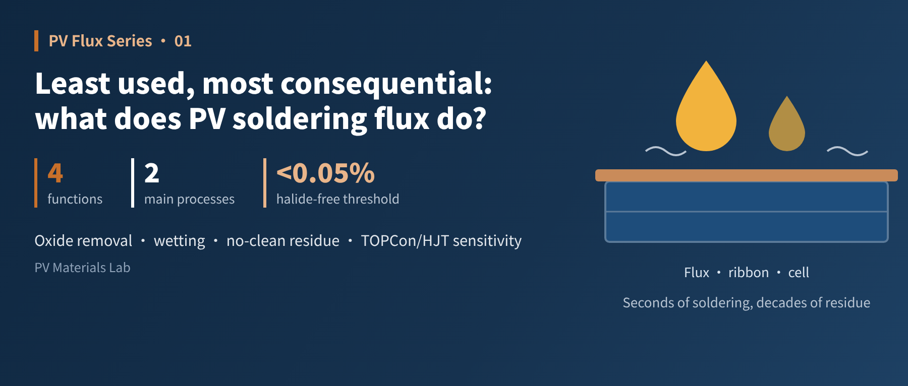
Flux often does not even get its own line in a module BOM, yet it decides whether stringing works at all — and its residue is sealed into the module by lamination, staying there for two or three decades. In this first article of our PV soldering flux series, we explain four things: why soldering cannot do without flux, what it actually does during soldering, where it appears in module production, and how PV flux differs from flux used in electronics.
In a module bill of materials, glass, cells, encapsulant, frame, ribbon and junction box are the headline items; flux often does not even get its own line. But anyone who has worked on stringing knows that when flux goes wrong, the result ranges from cold joints and failed pull tests to whole batches of modules losing power after damp heat testing. Our last series covered ribbon; this series turns to its "partner", flux. The first article answers the most basic question: what does it actually do?
01Why soldering needs flux
Start with an everyday observation: drop molten solder onto a dirty piece of metal and it tends to bead up into a ball that falls off at a touch; on a clean, activated surface it spreads out quickly and, once cooled, is firmly "grown" onto it. The difference between these two states is wetting.
Soldering is, at heart, a metallurgical bond between molten solder and the base metal at their interface, forming a very thin layer of intermetallic compound (IMC). For this to happen, the solder must meet the base metal "face to face". The problem is that almost no metal surface is bare:
- Ribbon surface: the tin coating slowly oxidises during storage and unwinding, forming a tin oxide film;
- Cell busbars / pads: the surface of fired silver paste is not pure silver and may carry glass phases, organic residues and adsorbed contamination;
- The heating itself: the higher the temperature, the faster oxidation proceeds, and new oxide keeps forming during the few seconds of soldering.
Although this oxide film is only nanometres thick, it is enough to separate molten solder from the substrate. The solder cannot "see" the metal underneath, so it neither spreads nor bonds. This film is the problem flux exists to solve.
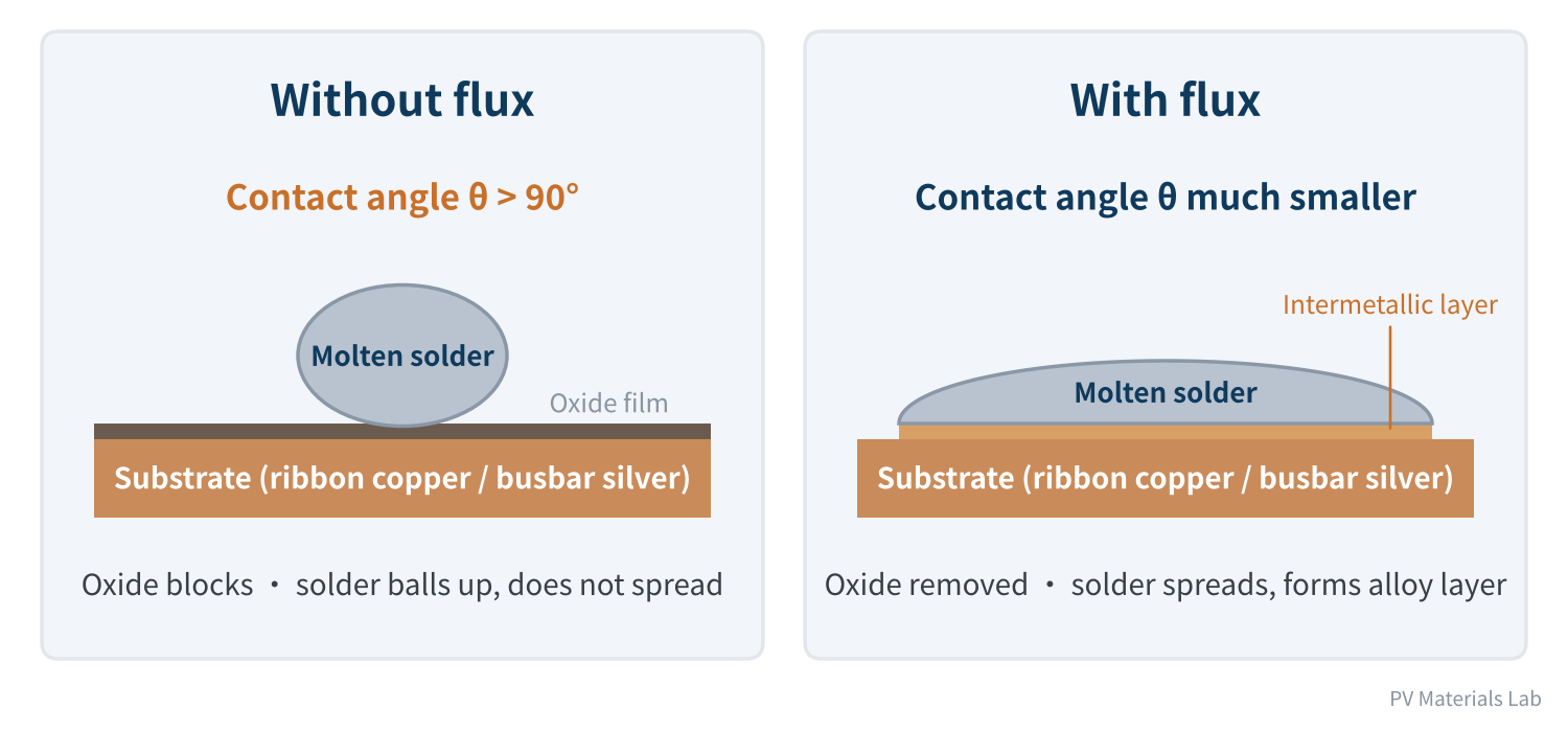
Figure 1 Wetting of molten solder with and without flux (schematic)
Without flux, an oxide film sits between solder and metal. The first job of flux is to remove that film at the moment of soldering.
02Four things flux does during soldering
Broken down, flux does four things. The first is the core function, the second its result, and the last two support the process.
- Removing the oxide film: the activators in the flux (mostly organic acids in PV fluxes) react with surface oxides when heated, producing compounds that can be displaced or decomposed and exposing clean metal.
- Promoting wetting: once the surface is clean, interfacial tension between solder and substrate drops, the contact angle shrinks, and solder can spread and penetrate the gap between ribbon and busbar.
- Shielding from air: during heating, the flux and its film-forming components cover the joint area, reducing contact with air and preventing the freshly cleaned surface from re-oxidising at high temperature.
- Aiding heat transfer: liquid flux fills the tiny gaps between ribbon and cell, spreading heat more evenly so the solder melts and wets at the same time.
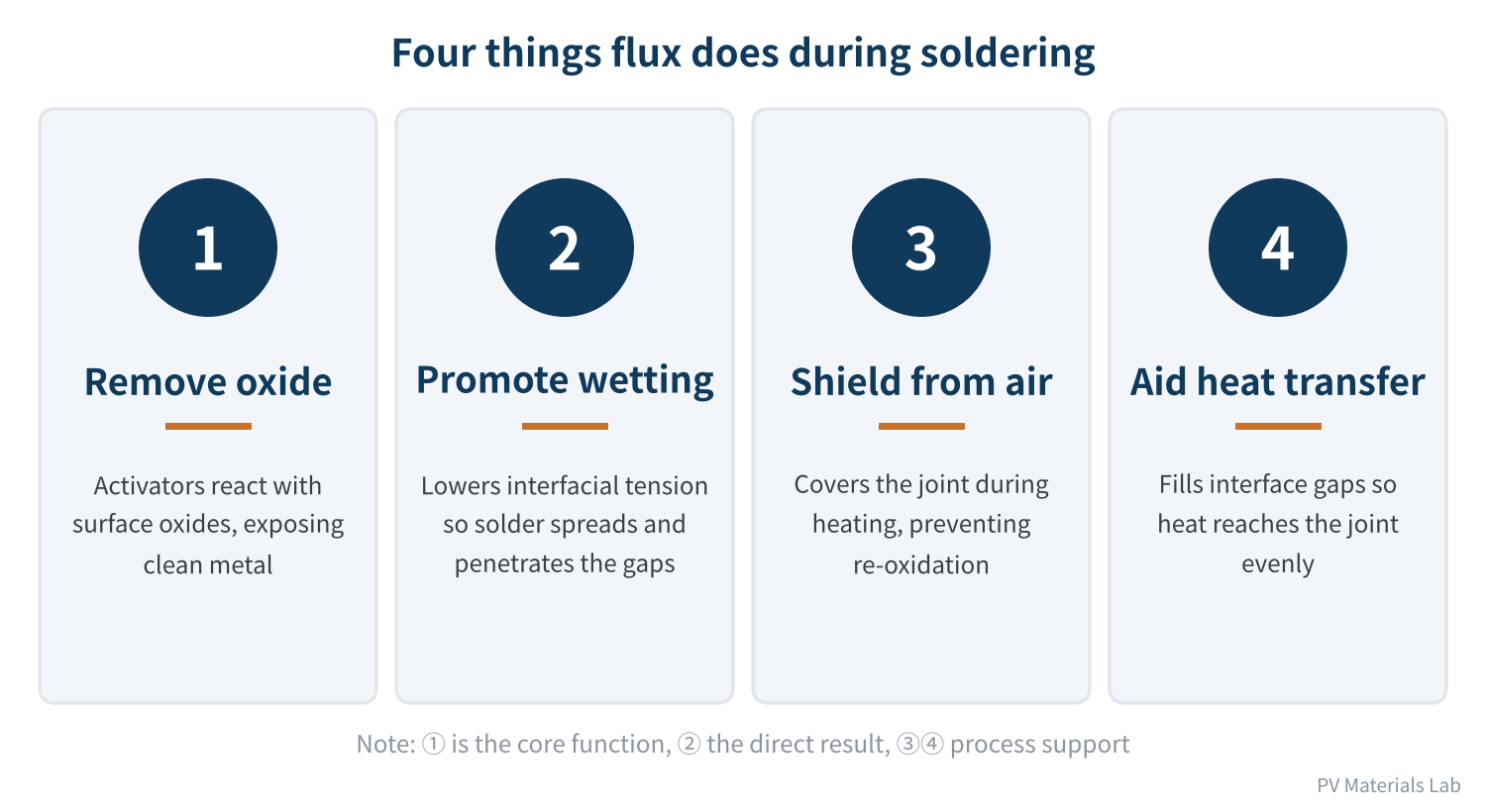
Figure 2 Four functions of flux during soldering
One point is often overlooked: flux "activity" cuts both ways. The more active the flux, the more thoroughly it removes oxide and the wider the soldering window; but the more likely its residue is to "keep working" after soldering, corroding metal in humid conditions. The core challenge of flux formulation is balancing "solders well" against "is safe to leave behind". We will return to this in the composition and reliability articles.
03Where flux is used in a module
On a typical crystalline silicon module line, flux appears mainly in two processes: stringing and busbar soldering.
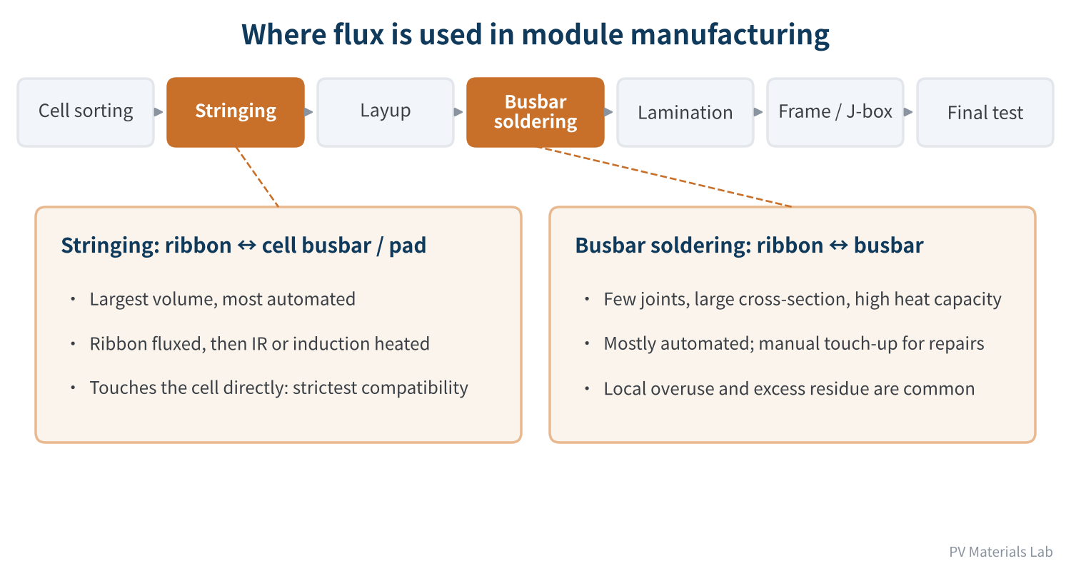
Figure 3 Where flux sits in module manufacturing
- Stringing: the largest use. Before entering the soldering zone, ribbon passes through flux (by dipping or spraying) and is then heated by infrared, induction or hot air and soldered to the cell busbars or pads. This step is fast, has many joints, and the flux touches the cell surface directly, so compatibility requirements are the strictest.
- Busbar soldering: joins the ribbons leading out of cell strings to the busbars. There are few joints, but the busbars have a large cross-section and high heat capacity, so excess flux and excess residue locally are more common.
- Repairs and manual touch-up: small in volume but the easiest to get out of control. Flux brushed on by hand tends to be applied "more rather than less", and residue can be far higher than in automated soldering.
From a materials perspective, ribbon and flux are partners: the ribbon supplies the solder, and the flux makes the solder bond. When the ribbon's coating composition, melting point or surface condition changes, the flux often has to change too. That is why we put the flux series straight after the ribbon series.
04Why "least used, most consequential"
Per module, the amount of flux is tiny and its share of module cost is very low; many companies do not even break it out in their BOM cost analysis. But its influence runs through the whole life of the module, from production to service.
| Dimension | Typical flux-related problems | Where it first shows up |
|---|---|---|
| Soldering yield | Cold joints, false joints, lifted ribbon, failed pull tests | Stringer, EL, pull test |
| Electrical performance | Poor contact at the solder interface, high series resistance | IV test, dark areas in EL |
| Appearance | White spots, darkening or crystalline residue around joints | Visual inspection before and after lamination |
| Long-term reliability | Residue corrodes fingers/electrodes in damp heat; series resistance rises, power drops | Accelerated ageing such as DH, field operation |
Table 1 Four ways flux affects a module
The first three are relatively easy to catch on the line. The fourth is the real headache.
PV modules almost all use no-clean flux: joints are not cleaned after soldering, and the residue is sealed straight into the module by the encapsulant and glass. Flux therefore has a dual identity — for the few seconds of soldering it is a process material; for the following two or three decades it is a residue inside the module.
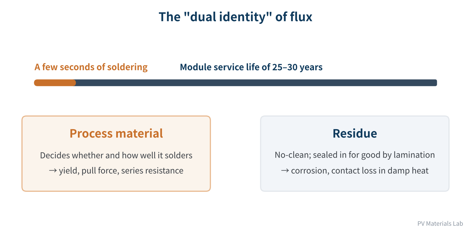
Figure 4 The dual identity of flux: a process material for seconds, a residue for decades
Research over the past two years has confirmed this repeatedly:
- TOPCon: a 2025 study by the University of New South Wales (UNSW) found that under damp heat, halogen-containing flux corrodes front-side metal contacts markedly more, but halogen-free flux also causes considerable degradation. The team recommended screening flux risk quickly with cell-level damp heat tests before encapsulation, and choosing formulations with as little halogen as possible and optimised acid content. Follow-up work by the team in late 2025 found that laser-assisted firing (LAF) clearly reduces, but does not eliminate, flux-induced contact corrosion: in an accelerated test of bare cells at 85 °C/85% RH for 45 hours, cells without LAF lost more than 40% of their efficiency with both halogen-containing and halogen-free flux.
- HJT: a study by a team at the Korea Electronics Technology Institute (KETI), published in Cell Reports Physical Science in 2025, found that organic acids in flux corrode the ITO electrode, with the rear ITO more vulnerable than the front. Lamination does not remove the residue, and modules with excess flux fell to about 70% of their power after 1,000 hours of damp heat. Samples where the flux was dried with hot air (80 °C or 100 °C for 60 seconds) before soldering showed essentially no EL dark spots after 1,000 hours of damp heat.
- Module failure analysis: in an earlier UNSW failure analysis of HJT glass-backsheet modules, two failure modes were attributed to the involvement of flux.
In other words, as cell technology moves from PERC to TOPCon and HJT, cells are becoming more sensitive to flux residue, and flux has gone from an auxiliary material that "just needs to solder" to one of the key materials for module reliability.
Flux acts in two phases: during soldering it determines yield and electrical performance; afterwards, as residue, it determines long-term reliability. The second is less visible and more damaging.
05How PV flux differs from electronics flux
Flux was not invented by the PV industry. It has a long history in electronics assembly (PCB soldering), with mature standards such as China's GB/T 9491-2021 Soldering Fluxes and the widely cited IPC J-STD-004 (currently Revision C). But PV modules are used very differently from electronic products, and that places special demands on flux.
| Item | Electronics assembly (PCB) | PV modules |
|---|---|---|
| Cleaning | Some processes clean after soldering | Essentially no cleaning; residue is sealed in by lamination |
| Solids content | Low to high all used | Mainly low solids; residue should be minimal |
| Halogens | Chosen by product class; both halogen-containing and halogen-free used | Trend towards halogen-free to reduce damp heat corrosion risk |
| Compatibility with | PCB substrate, solder mask, components | Cell surface (SiNx, ITO, fingers), EVA/POE encapsulant |
| Service environment | Mostly indoors or inside equipment | Outdoors: high temperature, high humidity, strong UV; 25–30 year life |
| Soldering speed | Varies by product | High-speed stringing; fast wetting and controlled volatilisation required |
Table 2 Electronics assembly flux versus PV flux
Two concepts will come up often in later articles:
- Low solids: solids content is the share of non-volatile material left after the solvent evaporates. The lower it is, the less residue. One international brand's dedicated PV flux, for example, lists a theoretical solids content of about 1.5% in its technical data sheet and emphasises zero halogen and suitability for spraying or dipping on stringers.
- Halide-free versus halogen-free: under the classification rules of IPC J-STD-004, a flux whose solids contain less than 0.05% (by weight) of combined halide ions (F⁻, Cl⁻, Br⁻, I⁻) is designated "0" — strictly speaking "halide-free". The "halogen-free" commonly cited in industry is a different measure, generally following the IEC 61249 series: chlorine and bromine each below 0.09%, combined below 0.15%, counting halogens in all forms. The two measure different things by different methods, so read technical data carefully. Halogens are strong activators, but halide ions in residue are also a main driver of corrosion.
So PV flux is not just electronics flux in new packaging. It must still wet quickly enough for high-speed stringing under the constraints of low solids and no halogens, while living peacefully with the cell surface and encapsulant for decades. These requirements pull against each other in formulation, and they are what the following articles will unpack one by one.
06Final thoughts
Back to the title: why is flux one of the "least used, most consequential" materials in a module?
- Little used: its quantity and cost share per module are very low, so it is easily overlooked in cost reduction and selection;
- Highly consequential: it decides whether soldering works at all, and then stays with the module for its whole life as residue;
- Increasingly sensitive: high-efficiency cells such as TOPCon and HJT are more sensitive to flux residue, so choosing the wrong flux costs more than before.
Once we understand what flux does, the natural next question is what it is made of. In the next article we will take a bottle of flux apart and look at the roles of solvents, activators, film formers and surfactants, and at the logic behind classifications such as rosin versus no-clean, alcohol-based versus water-based, and halogen-containing versus halogen-free.
If you have met flux-related "puzzles" on the production line, we would be glad to hear from you — good cases may feature in our later failure analysis article.
References
- GB/T 9491-2021 Soldering Fluxes, State Administration for Market Regulation and Standardization Administration of China, 2021 (in Chinese)
- IPC J-STD-004C with Amendment 1, Requirements for Soldering Fluxes, IPC, 2022
- Indium Corporation: Halide-Free vs. Halogen-Free: A Refresher, https://www.indium.com/blog/halide-free-vs-halogen-free-a-refresher/
- MacDermid Alpha: Kester SF800-LR Soldering Flux technical data sheet, 2021, https://www.macdermidalpha.com/sites/default/files/2022-04/Kester-SF800-LR-Soldering-Flux-EN-22Jan21-TB.pdf
- pv magazine: UNSW study shows impact of soldering flux on TOPCon solar cell degradation, 2025 (original: Assessing the impact of solder flux-induced corrosion on TOPCon solar cells, Solar Energy Materials and Solar Cells), https://www.pv-magazine-india.com/2025/08/18/unsw-study-shows-impact-of-soldering-flux-on-topcon-solar-cell-degradation
- A. Li, F. Rougieux, H. Wang, M. U. Khan, B. Hoex, C. Sen: Elucidating the Impact of Soldering Flux-Induced Degradation on the Reliability of TOPCon Solar Cells with and without Laser-Assisted Firing under Damp-Heat Stress, APVI Solar Research Conference, December 2025, https://apvi.org.au/solar-research-conference/wp-content/uploads/2025/12/48.pdf
- G. Park et al.: Soldering flux causes corrosion of indium tin oxide electrode in heterojunction solar cells, Cell Reports Physical Science, 2025, https://www.sciencedirect.com/science/article/pii/S2666386425002188
- pv magazine: Scientists warn of heat-induced failure risks in HJT glass-backsheet PV modules, 2023 (original: Four failure modes in silicon heterojunction glass-backsheet modules, Solar Energy Materials and Solar Cells)
A PV R&D and technology team with 10+ years of experience | In-depth technical knowledge sharing
Materials · Reliability · Failure Analysis · Standards & Certification · Products · Processes
Exploring AI + PV; collaboration welcome
Disclaimer:
1. Original content reflects the authors' personal views only, is for reference only and does not constitute investment advice.
2. Reposted and cited content is credited to its source, out of respect for original work.
3. Some content was produced with AI assistance (chart generation, data retrieval, concept explanations, etc.); the core framework and key content were written by our technical team and reviewed by people.
4. If anything is inaccurate or infringes your rights, please leave a message or contact us and we will deal with it.