
Cold Joints, Low Peel Strength, Blackened Joints: Is the Flux Really to Blame?
In brief
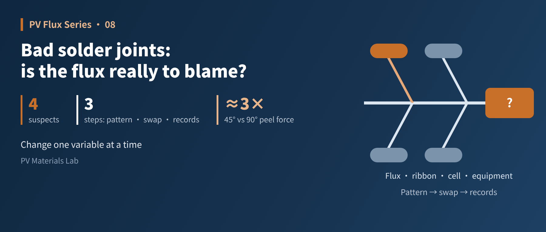
When stringing goes wrong, flux is usually the first suspect, but it is not always the real cause. This article first classifies common soldering defects, then uses a fishbone diagram to map four groups of suspects: flux, ribbon, cells, and equipment and process. It sets out a three-step troubleshooting method of "look at the pattern, swap, check the records", and explains how the fracture location in a peel test points to where the problem lies. It closes with a quick-reference table of flux-related defects for use on the line.
On the production line, when soldering goes wrong, flux is often the first thing blamed: try a new drum, add some thinner. Sometimes that works, but more often the problem comes back a few days later. Flux is a common cause of soldering defects, but not the only one. In this article we take the line's perspective and look at how to judge systematically whether a problem really is the flux.
01Classify the defect first: what are you actually seeing?
Before troubleshooting, describe the symptom clearly. "Bad soldering" is too vague, and different symptoms point to very different causes. Common soldering defects fall into these groups:
| Defect type | Typical features | Common inspection methods |
|---|---|---|
| Cold / false joint | Ribbon appears attached but has no reliable metallurgical bond; comes off at a touch or is partly unsoldered | EL, peel test, visual |
| Low peel strength | Low average peel force, or wide scatter along one ribbon | Peel test (state the peel angle) |
| Over-soldering | Temperature too high or time too long, causing breakage, microcracks or finger lift-off | EL, visual, microscopy |
| Abnormal joint appearance | Blackening, white spots or crystalline residue around the joint, or solder balls | Visual, microscopy |
| Ribbon offset / slip | Ribbon off the finger position, or moving after soldering | Visual, vision inspection |
Table 1. Classification of common soldering defects
Peel testing deserves a special note. EN 50461 sets a minimum of 1 N per mm of joint width but does not specify the peel angle. A Fraunhofer ISE study found that the same type of joint gives very different forces at different angles: about 9.7 N on average at 45° versus about 3.1 N at 90°, roughly three times as much, with about 2.5 N at 135° and 3.5 N at 180°. Before comparing peel data, always confirm that the peel angle, speed and fixture are the same. With fine round-wire ribbon, joint width is hard to define in the first place, and many companies set internal limits as force per wire instead, which makes it even more important to align definitions before comparing across plants.
02Four suspects
Soldering is the combined result of ribbon, cell, flux and equipment/process. A fishbone diagram maps the common causes:
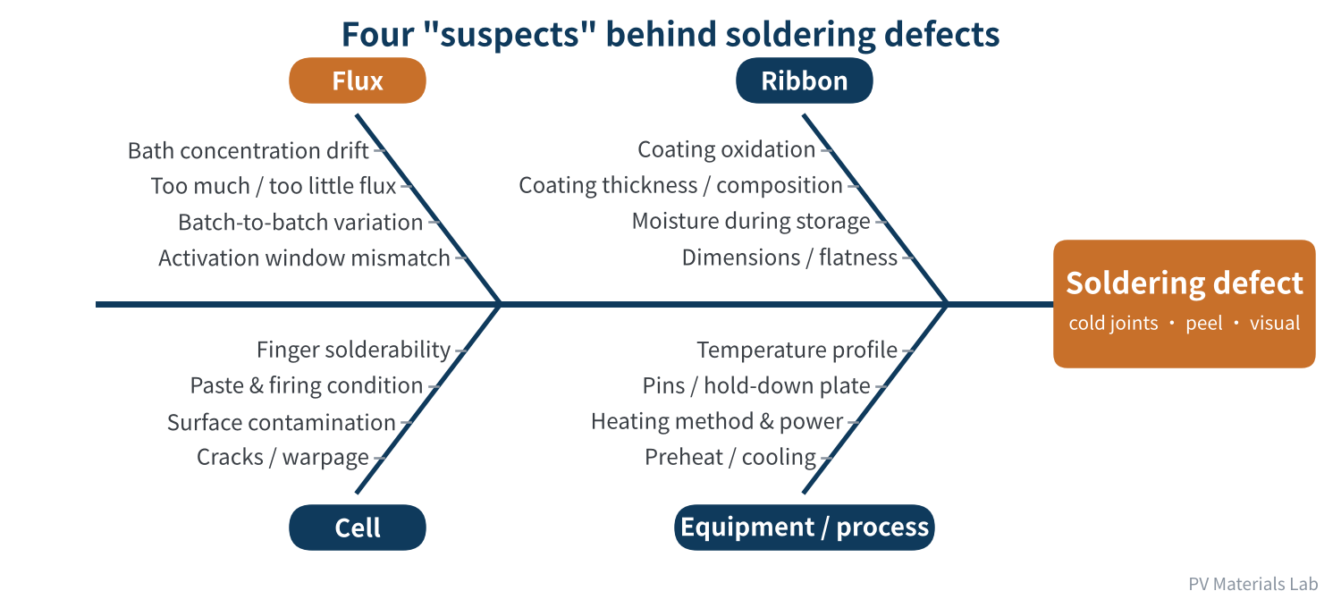
Figure 1. Four "suspects" behind soldering defects
- Flux: drift in bath concentration (evaporation, water uptake), too much or too little flux, batch-to-batch variation, activation window not matched to the temperature profile.
- Ribbon: coating oxidation, variation in coating thickness or composition, moisture during storage, poor dimensions or flatness. We covered these in detail in our ribbon series.
- Cell: poor finger solderability, abnormal paste or firing condition, surface contamination, and incoming issues such as microcracks and warpage.
- Equipment / process: temperature profile drift, pin or hold-down plate condition, heating power decay, changes in preheat and cooling settings.
These four groups often look alike: a cold joint may come from low flux concentration, from oxidised ribbon or from a drop in heating power. Drawing a conclusion from one symptom alone easily leads to "arresting the wrong suspect".
03A three-step method: pattern, swap, records
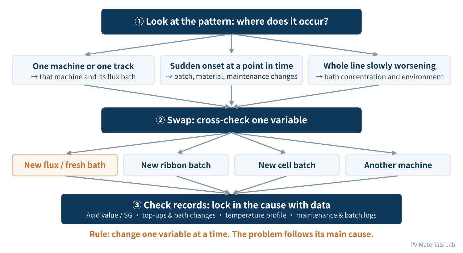
Figure 2. Three-step approach to troubleshooting soldering defects
- Step 1, look at the pattern: first establish where the problem is and when it started. If it is concentrated on one machine or track, check that equipment and its flux bath first. If it appeared suddenly after a certain point in time, check batch changes, material changes and maintenance around that time. If the whole line is slowly getting worse, check bath concentration and shop-floor temperature and humidity first.
- Step 2, swap: on the affected machine, change one variable at a time: a new drum of flux or a freshly made bath, a new ribbon batch, a new cell batch, or run the same materials on another machine. Change only one variable at a time. Whatever the problem follows is the main suspect.
- Step 3, check the records: use data to lock in the cause: bath acid value and specific gravity, top-up and bath-change logs, temperature profiles and heating power, maintenance logs, and material batch changes. The baselines and daily records recommended in articles 03 and 05 become decisive here.
These three steps pin most problems to one main cause. If the problem disappears after swapping the flux, send the old bath for testing and compare acid value, solids content and appearance to tell whether the issue lies in bath management or in the incoming batch.
The key to troubleshooting is controlling variables. Narrow the scope with the pattern, verify by swapping one thing at a time, then confirm with records, so that "we changed the flux and it happened to get better" does not mislead you.
04Reading the cause from the peel fracture
A peel test is more than one number. Once the ribbon is pulled off, the layer where it failed often says more than the force value itself.
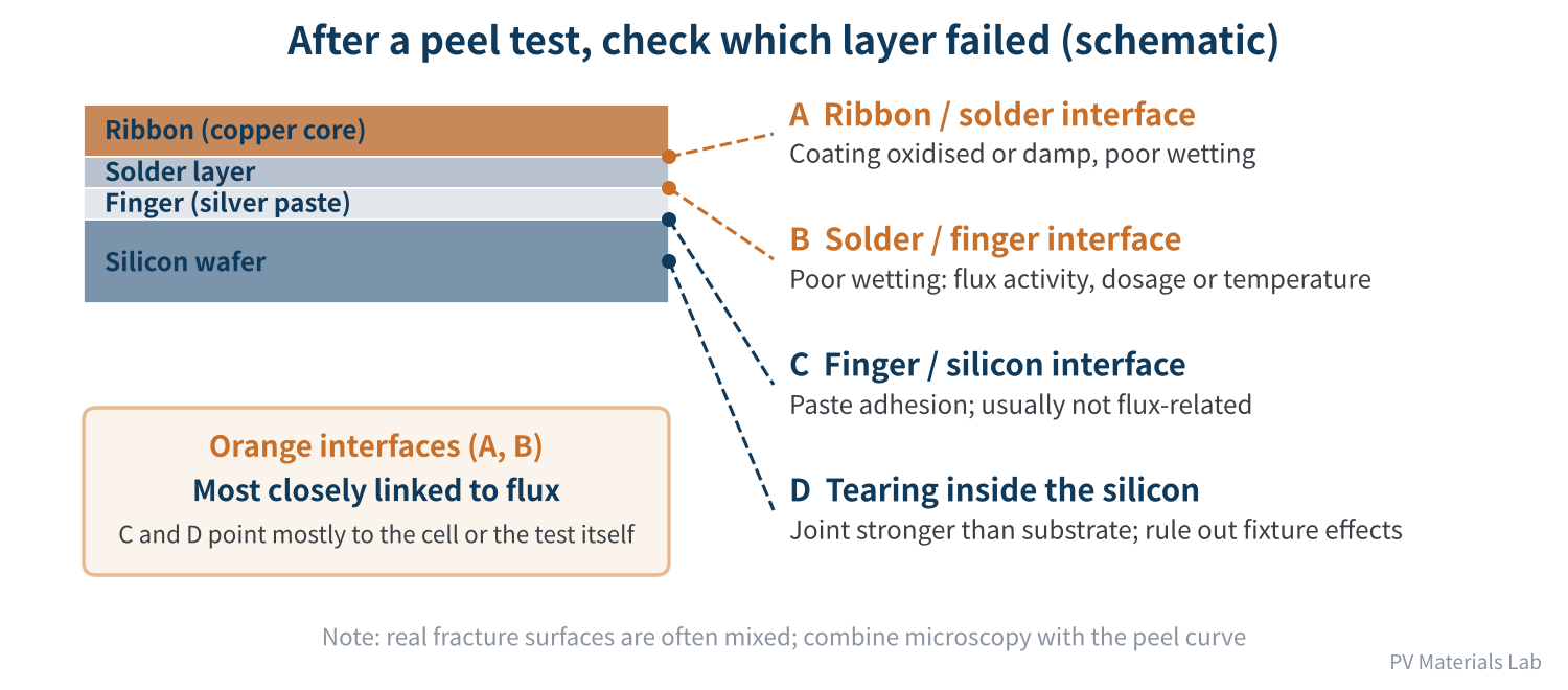
Figure 3. After a peel test, check which layer failed (schematic)
- Failure between ribbon and solder: poor bonding between the solder coating and the copper core, or at the coating surface; typical of oxidised or damp ribbon or insufficient wetting.
- Failure between solder and finger: the solder did not wet the finger well, and almost no solder remains on the finger surface. This is the failure location most closely linked to flux, usually from insufficient activity, too little flux or too low a temperature.
- Failure between finger and silicon: the finger is lifted together with the solder, exposing the wafer surface. This is usually a paste adhesion problem with no direct link to flux.
- Tearing inside the silicon: the joint is stronger than the substrate, but rule out artefacts from poor fixturing.
Real fracture surfaces are often a mix of modes, so combine microscopy with the peel curve. The Fraunhofer ISE study observed a uniform cohesive fracture inside the cell metallisation in all of its 180° peel tests. A separate study from a Korean group used shear tests to look at ageing: after 1,000 hours at 90–150°C, shear strength fell from about 240–270 MPa to about 130 MPa, the fracture location shifted between the solder/sintered-Ag and sintered-Ag/silicon interfaces, and the loss of strength came mainly from weakened bonding between sintered silver and silicon. Peel strength and fracture surfaces both change with ageing, so take the sample's history into account.
05Quick-reference table for flux-related defects
Finally, here is a quick-reference table of common flux-related defects for use on the line:
| Symptom | Possible flux-related cause | Suggested check |
|---|---|---|
| More cold joints on one machine | Low bath concentration on that machine, clogged nozzle or too little flux | Measure that bath's acid value, check nozzle or brush, compare with a fresh bath |
| Peel strength drops after a batch change | Flux batch variation | Compare COA with internal baseline; cross-solder old and new batches |
| White spots or heavy residue around joints | Too much flux, concentrated bath, high solids or water uptake | Measure acid value and solids, adjust dosage, watch how residue changes |
| Solder balls, spatter | Solvent or water not fully evaporated, insufficient preheat | Check preheat temperature and drying/blow-off; check the bath for water uptake |
| Ribbon slip or offset | Too much liquid flux reducing positional stability | Reduce dosage or add pre-solder drying and watch for improvement |
| Blackened joints | Residue overheated by excessive temperature, or abnormal activator decomposition | Check the temperature profile, rule out over-soldering, then compare with another flux |
| EL darkening near the ribbon after ageing | Flux overflow or residue corrosion (TOPCon and HJT are more sensitive) | Inspect for overflow traces under the microscope; compare in cell-level damp heat |
Table 2. Quick-reference table for flux-related defects
Note that the table lists only possible flux-related causes. The same symptoms may come from ribbon, cells or equipment. Use the table to narrow the scope; the final conclusion still has to be confirmed by swap testing.
Classify the symptom first, read the cause from the pattern, lock it in by swapping, and confirm it with records. The peel fracture surface is an important clue to wetting problems.
06Final thoughts
Three things to remember when troubleshooting soldering defects:
- Don't jump to conclusions: flux is a common suspect, but cold joints and low peel strength can just as well come from ribbon, cells or equipment;
- Control variables: look at the pattern, swap, check the records, and change one variable at a time so the problem "follows its cause";
- Read the fracture: failure between solder and finger is most likely linked to flux wetting; failure between finger and silicon points more to the cell paste.
This article covered defects you can see directly on the line. Another class of problem is more hidden: modules look fine when they ship, but problems emerge gradually in DH, TC and HF ageing tests or in the field. In the next article we look at the role of flux in module reliability, using failure analysis cases to show how corrosion, electromigration and rising series resistance develop step by step.
Do you have a "secret weapon" for troubleshooting soldering defects? We would be glad to hear from you.
References
- U. Eitner, L. C. Rendler: Peel Testing of Ribbons on Solar Cells at Different Angles: Consistent Comparison by Using Adhesive Fracture Energies, 29th EU PVSEC, Fraunhofer ISE, 2014, https://www.ise.fraunhofer.de/content/dam/ise/de/documents/publications/conference-paper/29-eupvsec-2014/Eitner_5DV340.pdf
- EN 50461: Solar cells — Datasheet information and product data for crystalline silicon solar cells (minimum peel force 1 N/mm)
- M.-S. Kang, Y.-J. Jeon, Y.-E. Shin: Bonding Strengths and Thermal Degradation of Photovoltaic Module Ribbon Solder Joints, International Journal of Precision Engineering and Manufacturing-Green Technology 6 (2019) 489–496, https://link.springer.com/article/10.1007/s40684-019-00045-0
- Renewable Energy World: Bond testing of solar cell interconnections
- pv magazine: New study confirms sensitivity of heterojunction solar cells to soldering flux, 2025
- pv magazine Australia: UNSW study shows impact of soldering flux on TOPCon solar cell degradation, 2025
A PV R&D and technology team with 10+ years of experience | In-depth technical knowledge sharing
Materials · Reliability · Failure Analysis · Standards & Certification · Products · Processes
Exploring AI + PV; collaboration welcome
Disclaimer:
1. Original content reflects the authors' personal views only, is for reference only and does not constitute investment advice.
2. Reposted and cited content is credited to its source, out of respect for original work.
3. Some content was produced with AI assistance (chart generation, data retrieval, concept explanations, etc.); the core framework and key content were written by our technical team and reviewed by people.
4. If anything is inaccurate or infringes your rights, please leave a message or contact us and we will deal with it.