
Fine at Shipment, Power Lost After Ageing: The Role of Flux in Module Reliability
In brief
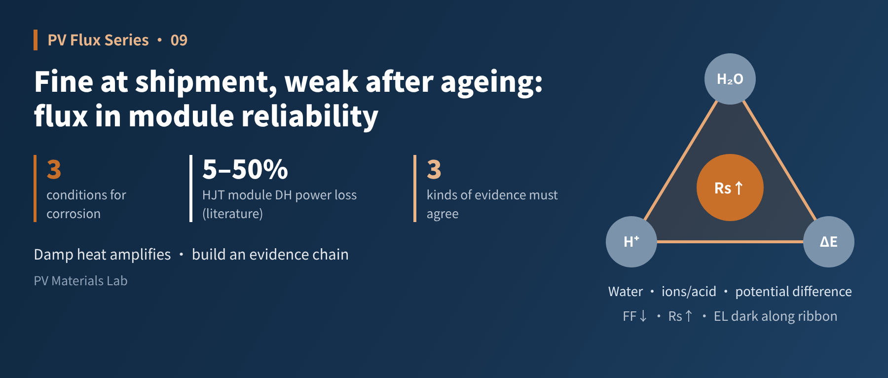
Many flux-related problems cannot be seen on the production line. They emerge gradually in ageing tests such as damp heat and thermal cycling, or in the field. This article first looks at how flux shows up in different reliability tests, then uses the "three conditions for corrosion" to explain how residue takes part in corrosion. It maps the path from residue to power loss and its typical "signature", reviews four failure cases from published studies, and closes with an analysis workflow for flux-related failures: location evidence, composition evidence and reproduction experiments must all agree before drawing a conclusion.
The previous article covered soldering defects you can see directly on the line. This one looks at a more hidden kind of problem: modules ship with clean EL images and full power, yet after a few hundred hours of damp heat, or a few years in the field, dark areas appear along the ribbon and power keeps falling. The impact of flux on reliability is often "paid later". Let us look at how it happens and how to analyse it.
01How flux shows up in reliability tests
Module design qualification includes many tests, and flux does not play a big role in every one. Roughly, by degree of relevance:
| Test | Main way flux has an effect | Relevance |
|---|---|---|
| Damp heat (DH) | Residue absorbs water and takes part in corrosion, attacking finger contacts, ITO and solder and raising series resistance | High |
| Thermal cycling (TC) | Soldering quality sets the initial state of the joint; poorly wetted joints crack more easily under thermal stress | Medium (indirect) |
| Humidity freeze (HF) | Moisture plus freeze–thaw cycles; weak interfaces formed by residue may worsen delamination | Medium |
| UV | Reactions between residue and encapsulant under light may cause yellowing near the ribbon | Medium (see article 07) |
Table 1. How flux relates to each reliability test
As the table shows, damp heat is the main "amplifier" of flux problems. The rest of this article follows corrosion as the main thread.
02Three conditions for corrosion: what flux supplies
Metal corrosion inside a module usually needs three conditions at once: water, ions or acid, and a potential difference between metals.
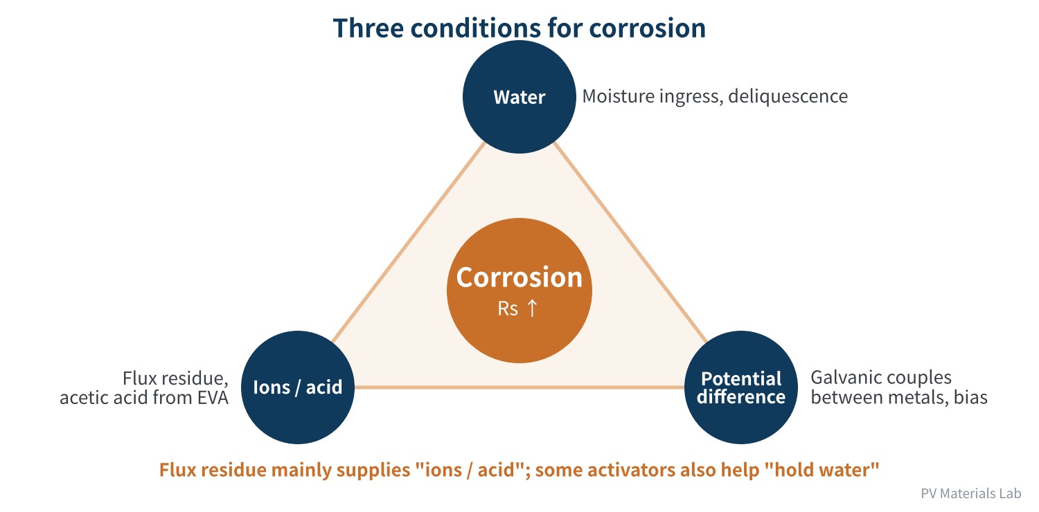
Figure 1. Three conditions for corrosion
- Water: in damp heat, moisture gradually enters the module. As article 07 noted, some organic acid activators deliquesce at around 85% RH, effectively "holding water" on the metal surface.
- Ions / acid: organic acids and halide ions in flux residue, together with acetic acid from EVA, form the active ingredients of the electrolyte.
- Potential difference: a module contains silver, copper, tin, lead and other metals, and wherever they touch they form galvanic couples. Tin and lead are more active than silver and copper, so they act as anodes and corrode first. A Korean group's work on corrosion of 62Sn36Pb2Ag solder in field-operated modules built its mitigation approach on exactly this mechanism.
Of the three conditions, flux mainly supplies "ions / acid", and some activators also help "hold water". Removing any one condition slows corrosion markedly, which is why low-halogen, low-acid and low-residue fluxes, and encapsulation with better moisture barriers, all help.
03From residue to power loss: the path and its "signature"
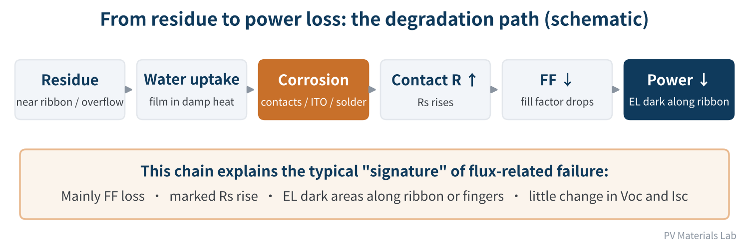
Figure 2. From residue to power loss: the degradation path (schematic)
In damp heat the residue absorbs water and forms a very thin liquid film. Acid and ions in the film corrode finger contacts, ITO or solder. Once the contact interface is damaged, contact resistance rises and module series resistance increases with it, finally showing up as lower fill factor and power loss.
This path gives flux-related failures a typical "signature":
- Electrical: mainly FF loss, with a marked rise in series resistance and relatively little change in open-circuit voltage and short-circuit current. Studies of solder corrosion likewise find that power loss after damp heat comes mainly from FF loss caused by higher series resistance.
- EL image: dark areas follow the ribbon, the fingers or the places where flux overflowed, rather than being scattered at random.
- Time: initial tests are normal, and degradation grows with damp-heat duration.
The signature can also be used to rule things out. A 2024 damp-heat study of HJT modules by France's CEA found that sodium migrating from soda-lime glass into the cells mainly destroyed passivation, showing up as a large drop in short-circuit current (up to 57.6% power loss after 1,500 hours, with Isc down 43.4%). If degradation is dominated by short-circuit current, suspect sodium and passivation before flux.
"Mainly FF loss + rising series resistance + EL darkening along the ribbon + worsening with damp-heat time" is the typical combination for flux-related corrosion, but it still needs evidence to confirm.
04Failure cases from four published studies
Below are four published cases related to flux or solder-joint corrosion, for reference.
| Case | Samples and conditions | Main symptoms | Link to flux |
|---|---|---|---|
| TOPCon cells (UNSW) | Two commercial no-clean fluxes, unencapsulated cells, 100°C/85% RH damp heat | Severe corrosion of front Ag-Al contacts; rear Ag contacts barely degraded | Halogen-containing flux was more corrosive, but a low-halogen malic acid flux also caused clear degradation |
| HJT cell ITO (KETI, Korea) | Flux deliberately allowed onto the ITO surface during soldering, damp heat | Severe loss of ITO conductivity; dark EL spots where residue was not removed, worse on the rear | The more acidic flux degraded most; samples dried and blown off before soldering barely degraded |
| HJT glass-backsheet modules (UNSW) | Damp heat for about 1,500–4,000 hours | Four failure modes with relative power loss of about 5–50% | Two attributed to flux: darkening around ribbon interconnects (~1,500 h, ~5%) and between busbars (~2,500 h, ~50%) |
| Field-operated modules (Korea) | SnPbAg solder interconnects, analysis after field ageing plus damp-heat validation | Sn and Pb corrosion, rising Rs, FF loss; in modules after 6 years in the field, Sn and Pb also found on the Ag fingers | Mainly galvanic corrosion, showing that long-term solder-joint corrosion risk is real |
Table 2. Published failure cases related to flux or solder-joint corrosion
These cases share several lessons:
- Clear location pattern: degradation concentrates at the ribbon, the finger contacts and where flux overflowed, matching the signature in Figure 2.
- Acidity and halogens are key variables: the TOPCon and HJT studies point to the same conclusion: the stronger the acidity and the more halogen, the worse the degradation.
- Process can mitigate: drying and blowing off before soldering and controlling dosage to avoid overflow both reduce the risk significantly. The Korean group also tried adding sacrificial metal to modules. In follow-up work, mini-modules with Al-3Mg and similar aluminium-alloy sacrificial anodes had a series resistance of about 46.7 mΩ after 1,500 hours of damp heat, versus about 52.2 mΩ without an anode, and retained more power. Blocking corrosion electrochemically is a viable approach.
- Accelerated tests may not reproduce everything: the researchers linked the Sn and Pb migration seen in modules after 6 years in the field to "light-induced plating" under sunlight, and it did not appear under standard accelerated test conditions. Passing lab tests does not guarantee trouble-free field performance.
Note that the authors of the HJT module study also cautioned that their experimental design cannot establish exactly how each failure mode occurred. Literature cases help build a framework for judgement, but each specific problem still needs its own analysis.
05How to do the failure analysis: three kinds of evidence, none optional
When a module shows suspected flux-related degradation in ageing tests, we suggest the following workflow:
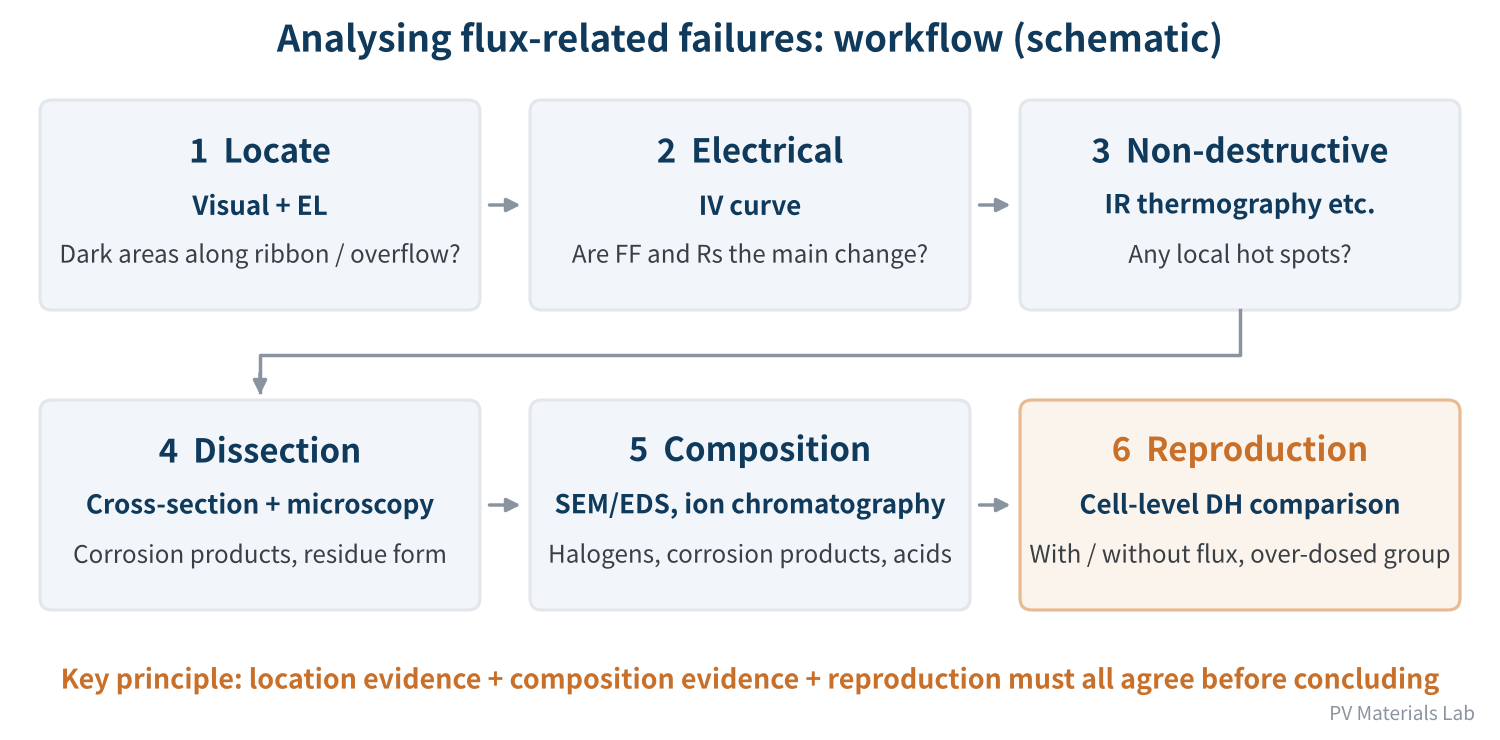
Figure 3. Analysing flux-related failures: workflow (schematic)
- Location and electrical: use visual inspection and EL to locate the dark areas, then check the IV curve to see whether FF and series resistance are the main changes.
- Non-destructive and dissection: if needed, use IR thermography to look for local heating, then open a window or cut a cross-section in the suspect area and examine corrosion products and residue under the microscope.
- Composition: use SEM/EDS to look at corrosion products and element distribution, paying particular attention to halogens; if needed, analyse ions and organic acids in the residue by ion chromatography or similar methods.
- Reproduction: with cells and ribbon from the same batch, make samples with flux, without flux and with excess flux, and compare them in cell-level damp heat to see whether the same failure pattern reappears.
Concluding that a failure is flux-related needs three kinds of evidence that agree: location (the failure is linked to the ribbon or overflow), composition (halogens or flux-related residue components are detected) and reproduction (adding flux reproduces the same symptom). With only one of them, problems in the encapsulant, paste or solder are easily misattributed to flux.
Flux-related failures have a clear signature, but a signature is only a clue. Location, composition and reproduction evidence must all agree before drawing a conclusion.
06Final thoughts
Three things to remember about the role of flux in module reliability:
- Damp heat is the amplifier: flux problems emerge mainly in DH, with indirect effects in TC, HF and UV;
- Corrosion has three conditions: water, ions/acid and potential difference; flux mainly contributes ions and acid, and some activators also help hold water;
- Analysis needs an evidence chain: FF-dominated loss, rising series resistance and EL darkening along the ribbon are the typical signature, but confirming the cause needs composition evidence and reproduction experiments.
That concludes the reliability part of the series. Next comes the industry part: knowing the risks flux can bring, how should a module maker select and qualify a new flux? In the next article we look at flux selection and qualification, including supplier evaluation, DOE validation, pilot runs and the switch to mass production, and change management.
Have you done failure analysis involving flux? What evidence finally confirmed the cause? We would be glad to hear from you.
References
- pv magazine Australia: UNSW study shows impact of soldering flux on TOPCon solar cell degradation, 2025
- G. Park et al.: Soldering flux causes corrosion of indium tin oxide electrode in heterojunction solar cells, Cell Reports Physical Science, 2025, https://www.sciencedirect.com/science/article/pii/S2666386425002188
- C. Sen, H. Wang, X. Wu et al.: Four failure modes in silicon heterojunction glass-backsheet modules, Solar Energy Materials and Solar Cells 257 (2023) 112358, https://www.sciencedirect.com/science/article/pii/S0927024823001794
- L. Pirot-Berson et al.: Failure modes of silicon heterojunction photovoltaic modules in damp heat environment: Sodium and moisture effects, Solar Energy Materials and Solar Cells 278 (2024) 113190, https://www.sciencedirect.com/science/article/abs/pii/S0927024824005026
- J.-H. Kim, J. Park, D. Kim, N. Park: Study on Mitigation Method of Solder Corrosion for Crystalline Silicon Photovoltaic Modules, International Journal of Photoenergy, 2014, DOI: 10.1155/2014/809075
- W. Oh et al.: Migration of Sn and Pb from Solder Ribbon onto Ag Fingers in Field-Aged Silicon Photovoltaic Modules, International Journal of Photoenergy, 2015, DOI: 10.1155/2015/257343
- W. Oh, S.-I. Chan: Corrosion mitigation of photovoltaic ribbon using a sacrificial anode, Journal of the Korea Academia-Industrial Cooperation Society 18(3) (2017) 681–686 (in Korean)
- V. Verdingovas, M. S. Jellesen, R. Ambat: Solder Flux Residues and Humidity-Related Failures in Electronics, Journal of Electronic Materials 44(4) (2015) 1116–1127
- IEC 61215-2:2021, Terrestrial photovoltaic (PV) modules — Design qualification and type approval — Part 2: Test procedures
A PV R&D and technology team with 10+ years of experience | In-depth technical knowledge sharing
Materials · Reliability · Failure Analysis · Standards & Certification · Products · Processes
Exploring AI + PV; collaboration welcome
Disclaimer:
1. Original content reflects the authors' personal views only, is for reference only and does not constitute investment advice.
2. Reposted and cited content is credited to its source, out of respect for original work.
3. Some content was produced with AI assistance (chart generation, data retrieval, concept explanations, etc.); the core framework and key content were written by our technical team and reviewed by people.
4. If anything is inaccurate or infringes your rights, please leave a message or contact us and we will deal with it.