
Flux on the Stringer: How to Apply It, How Much to Use, How to Manage It, and How to Match the Temperature
In brief
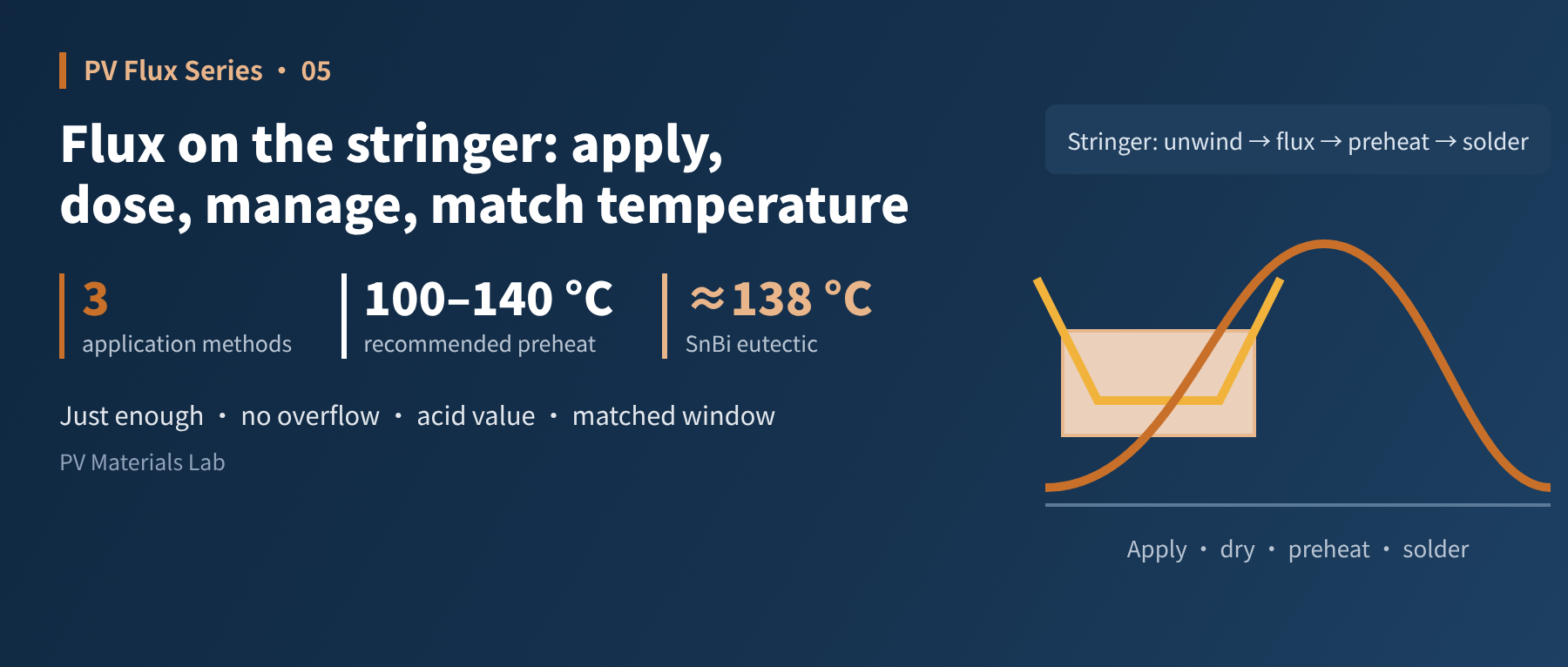
The same flux can give very different results on different stringers and different shifts. The problem is usually not the flux itself but the process. Following the stringing process, this article explains where flux comes in, the characteristics of three common application methods, what too much or too little flux leads to, how the bath evaporates and absorbs water in use and how to manage it, and finally how flux must match preheat and soldering temperatures — especially the new demands of low-temperature soldering. This is the fifth article in our PV soldering flux series.
The first four articles were about flux "itself": what it does, what it is made of, its indicators and its tests. From this article on, we put it on the production line. Anyone who has worked in process engineering has probably seen this: the same drum of flux behaves differently on a different machine or a different shift. Flux is a "material", but more than half of its performance depends on "process". This article follows the stringing process to see what needs managing at each step.
01Where flux comes in during stringing
On a typical ribbon stringer, the ribbon is unwound from the spool and straightened, passes through the flux application station, is cut to length and laid up with cells, then goes through preheat and soldering, and finally cools before EL inspection. Some machines or processes add a drying or blow-off step after fluxing.
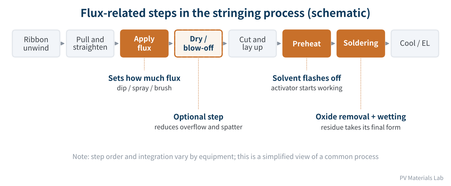
Figure 1 Flux-related steps in the stringing process (schematic)
From the flux's point of view, the process breaks down into four key actions:
- Application: decides how much flux the ribbon carries; the source of dosage control.
- Drying / blow-off: removes excess solvent and droplets early, reducing later overflow and spatter.
- Preheat: the solvent evaporates further and the activator starts to work.
- Soldering: the activator finishes removing oxide, the solder melts and wets, and the residue takes its final form.
02Three common application methods
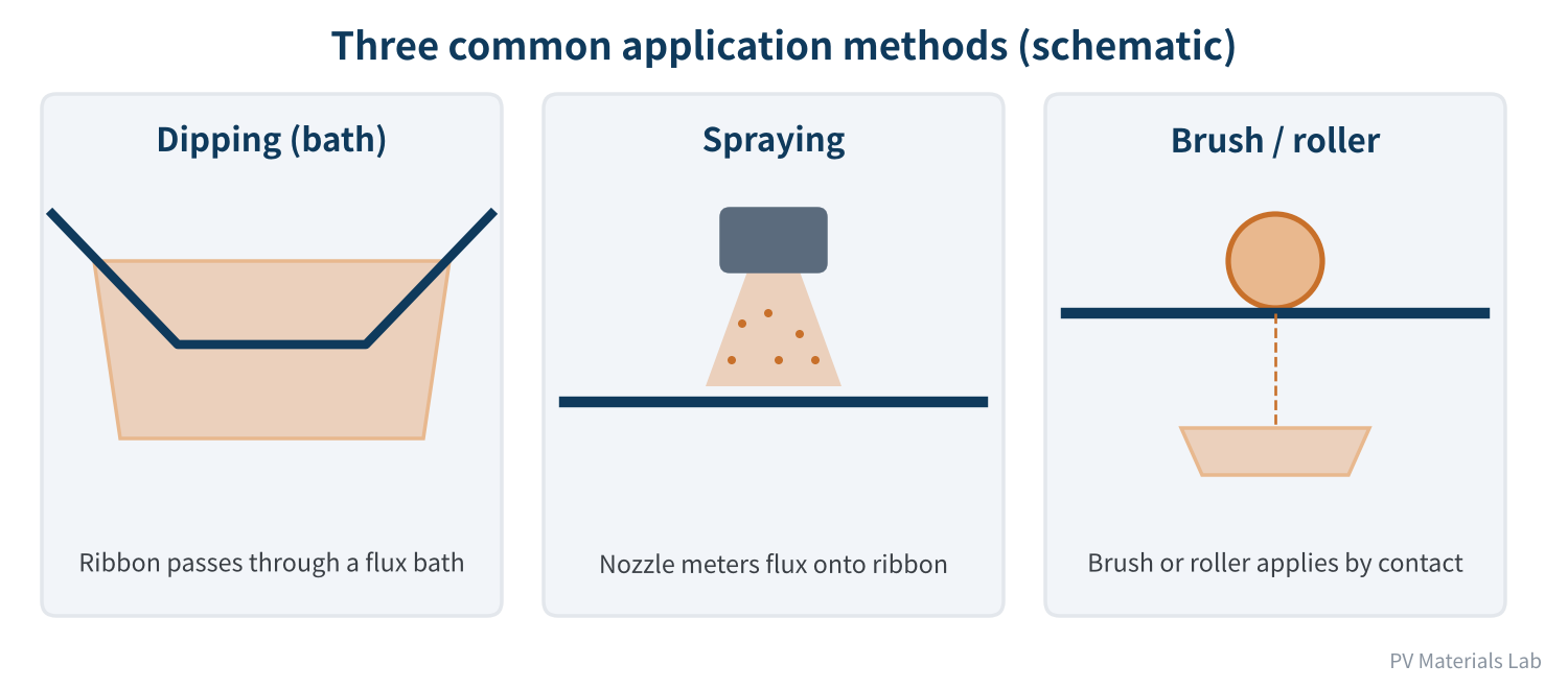
Figure 2 Three common application methods (schematic)
| Item | Dipping (bath) | Spraying | Brush / roller |
|---|---|---|---|
| Principle | Ribbon passes through a flux bath and picks up liquid | Atomising nozzle meters flux onto the ribbon | Brush or roller transfers flux by contact |
| Uniformity | Good, full-surface coverage | Depends on nozzle condition and atomisation | Affected by brush wear and pressure |
| Dosage control | Mainly via line speed, immersion length and pick-up | Adjustable flow, higher precision | Harder to control precisely |
| Evaporation and water uptake | Large open bath surface; needs close management | Reservoir relatively closed | Smaller pick-up bath |
| Main maintenance | Level, concentration, contamination; regular bath changes | Nozzle clogging, atomisation | Brush cleaning and replacement |
Table 1 Comparison of three common application methods
No method is best in every case; what matters is matching the equipment cycle time, ribbon type and flux characteristics. The flux for multi-busbar fine round wire ribbon mentioned earlier, for example, lists dipping, soaking and spraying as suitable methods, and notes that flux heating is generally not needed in wire dip tanks (about 25–35 °C if heating is preferred). During selection, treat the "recommended application method" as one of the matching conditions to confirm.
03Dosage: too much and too little both cause problems
There is no universal "right amount" of flux, but the consequences of straying from the right range are clear:
| Dosage | Typical symptoms | Underlying cause |
|---|---|---|
| Too little | Cold joints, low and scattered pull force, local dark areas in EL | Oxide not fully removed; solder does not wet fully |
| Too much | White spots or crystalline residue around joints; ribbon slipping or shifting | Excess residue; excess liquid reduces ribbon-to-finger positioning stability |
| Too much (overflow) | Flux marks on the cell surface; EL dark spots after ageing | Excess flux flows beyond the joint and contacts the cell surface directly |
| Uneven | Pull force varies along the same ribbon | Partly clogged nozzle, worn brush or ribbon vibration |
Table 2 Typical symptoms and causes of incorrect flux dosage
"Overflow" is the easiest to overlook and potentially the most costly. A 2025 study of HJT cells by a team at KETI in Korea found that flux overflowing onto the ITO surface corrodes it under damp heat — the rear ITO especially — raising series resistance. Lamination did not remove the residue, and modules with excess flux fell to about 70% of their power after 1,000 hours of damp heat. Samples where the flux was dried and the excess blown off with hot air (80 °C or 100 °C for 60 seconds) before soldering showed essentially no EL dark spots after 1,000 hours of damp heat. The study also observed that more acidic fluxes caused more degradation.
Fine round wire ribbon and multi-busbar designs make the problem more acute: the finer the ribbon and the more joints there are, the less flux is needed per unit area — and the lower the tolerance for "a bit extra". The fine-wire ribbon flux mentioned above highlights "reduced placement slipping for improved production yields" as a main benefit, and advises applying flux only to the areas being soldered.
The goal of dosage control is not "the less the better" but "just enough to solder, with as little overflow as possible". Drying and blowing off before soldering is an effective way to control overflow.
04Bath management: evaporation, water uptake and top-ups
In article 3 we did the sums: when the solvent of a low-solids flux evaporates, acid value changes markedly while specific gravity barely moves. This matters a great deal for line management. In use, the flux bath keeps changing in several ways:
- Solvent evaporation: open baths, heat inside the machine and extraction all speed up evaporation of alcohol solvents, raising the concentration of active components.
- Water uptake: alcohol solvents absorb moisture from the air, especially in humid seasons. Water affects evaporation behaviour and in severe cases causes spatter during soldering.
- Contamination build-up: oxides, debris and dust from the ribbon surface gradually enter the bath, discolouring it and making it cloudy.
AIM's data sheet for a low-solids flux states plainly that because the solids content is low, controlling automatic equipment by specific gravity is usually ineffective and titration is needed instead; for foam fluxing it recommends titrating at least once an hour and periodically adding thinner to replace evaporation losses. For these changes, we suggest a simple daily control checklist:
| Control item | Recommended practice |
|---|---|
| Concentration monitoring | Mainly acid value titration, with specific gravity as support; test and record at fixed intervals |
| Top-up | Use the supplier's recommended thinner, never a substitute solvent; retest after topping up |
| Bath change | Replace the whole bath at set intervals or on visible change (discolouration, cloudiness, sediment) |
| Limit evaporation and water uptake | Cover the bath where possible to reduce open area; watch workshop temperature and humidity |
| Records and handover | Record test values, top-up amounts and anomalies every shift; check at shift handover |
Table 3 Daily control checklist for the flux bath
Many "good on day shift, bad on night shift" problems turn out to be bath management issues: late top-ups, the wrong solvent added, or bath change intervals stretched. With good bath management, flux-related soldering anomalies can often be cut by more than half.
05Temperature matching: preheat, soldering and the activation window
As article 2 explained, the activator has a "working window": it should become fully active from late preheat to around solder melting, and be consumed or decomposed as far as possible afterwards. Flux must therefore be considered together with the stringer's temperature profile.
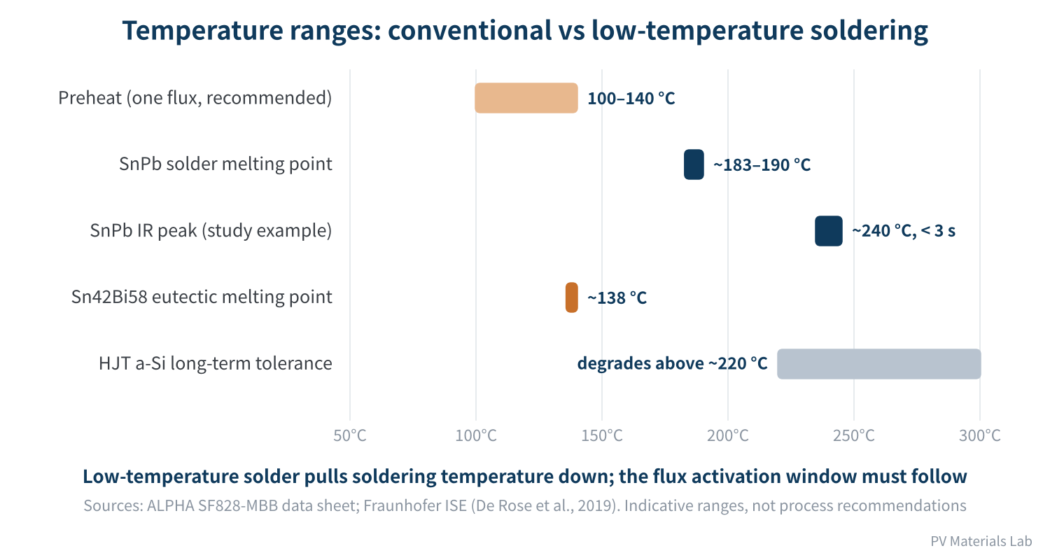
Figure 3 Temperature ranges for conventional and low-temperature soldering
- Preheat: preheat lets the solvent evaporate fully before soldering and evens out the temperature of cells and ribbon. Too little preheat and the solvent vaporises violently at the moment of soldering, causing spatter and voids; too much and the activator may be "spent" early, with little left by the time soldering starts. One PV flux, for example, recommends a preheat of about 100–140 °C.
- Soldering: conventional tin-lead solder (Sn60Pb40/Sn63Pb37) melts at about 183–190 °C. The flux data sheet above gives no specific soldering temperature, only a recommended soldering time of about 2,000–2,800 milliseconds for SnPb ribbon and the advice to use standard reflow temperatures. For reference, in Fraunhofer ISE's infrared soldering study of HJT cells, a peak of about 240 °C for under 3 seconds was enough to form void-free joints with Sn60Pb40 ribbon. Different heating methods (contact, infrared, induction, hot air) heat at different rates and with different temperature distributions, which affects the timing of flux evaporation and activation; re-confirm after changing heating method.
- Low-temperature soldering: the amorphous silicon passivation layers of HJT cells are not heat-resistant. Fraunhofer ISE's research notes they degrade severely when exposed above about 220 °C for longer durations. Temperature-sensitive cells such as HJT therefore often use lower-melting tin-bismuth solders — the Sn42Bi58 eutectic, for example, melts at about 138 °C. When soldering temperature moves down, the flux's activation window must move down with it; otherwise "the solder has melted but the flux has not started working yet".
Flux, ribbon and the stringer's temperature profile form one system. A change of ribbon, heating method or cell technology should each trigger re-validation of the flux.
06Final thoughts
To put flux to work on a stringer, four things need managing:
- Match the application method: dipping, spraying and brushing each have their characteristics; confirm against the equipment, ribbon and the flux's recommended method;
- Get the dosage "just right": too little gives cold joints; too much gives residue and overflow; drying and blow-off before soldering effectively reduce overflow;
- Manage the bath daily: monitor concentration mainly by acid value, standardise top-ups and bath changes, and limit evaporation and water uptake;
- Match the temperature: align preheat and soldering temperatures with the activation window; low-temperature soldering requires the flux to be adjusted accordingly.
The temperature section leads naturally into the next article: from PERC to TOPCon, HJT and BC, what new demands does each step in cell technology place on flux? And how will silver-coated copper, finer fingers, multi-busbar and 0BB change the role of flux? We will pick that up next time.
How often do you change the flux bath on your line? Which indicator tells you it is time to top up? We would be glad to hear from you.
References
- MacDermid Alpha: ALPHA SF828-MBB Liquid Flux technical bulletin, October 2023, https://www.MacDermidAlpha.com/sites/default/files/2024-01/ALPHA-SF828-MBB%20-Liquid-Flux-EN-04Oct23-TB.pdf; April 2026 edition, https://www.macdermidalpha.com/sites/default/files/2026-04/ALPHA-SF828-MBB-LFX-TDS-GL-EN-01Apr2026.pdf
- G. Park et al.: Soldering flux causes corrosion of indium tin oxide electrode in heterojunction solar cells, Cell Reports Physical Science, 2025, https://www.sciencedirect.com/science/article/pii/S2666386425002188
- A. De Rose et al.: Interconnection of Silicon Heterojunction Solar Cells by Infrared Soldering – Solder Joint Analysis and Temperature Study, 36th EU PVSEC, 2019, https://www.ise.fraunhofer.de/content/dam/ise/de/documents/publications/conference-paper/36-eupvsec-2019/DeRose_2CO114.pdf
- AIM Solder: NC263UR liquid flux technical data sheet (Chinese), https://www.aimsolder.com/sites/default/files/nc263ur_liquid_flux_chinese_tds.pdf
- pv magazine: UNSW study shows impact of soldering flux on TOPCon solar cell degradation, 2025, https://www.pv-magazine-india.com/2025/08/18/unsw-study-shows-impact-of-soldering-flux-on-topcon-solar-cell-degradation
A PV R&D and technology team with 10+ years of experience | In-depth technical knowledge sharing
Materials · Reliability · Failure Analysis · Standards & Certification · Products · Processes
Exploring AI + PV; collaboration welcome
Disclaimer:
1. Original content reflects the authors' personal views only, is for reference only and does not constitute investment advice.
2. Reposted and cited content is credited to its source, out of respect for original work.
3. Some content was produced with AI assistance (chart generation, data retrieval, concept explanations, etc.); the core framework and key content were written by our technical team and reviewed by people.
4. If anything is inaccurate or infringes your rights, please leave a message or contact us and we will deal with it.