
When Flux Residue Meets EVA and POE: The Compatibility Problems Behind Yellowing, Bubbles and Delamination
In brief
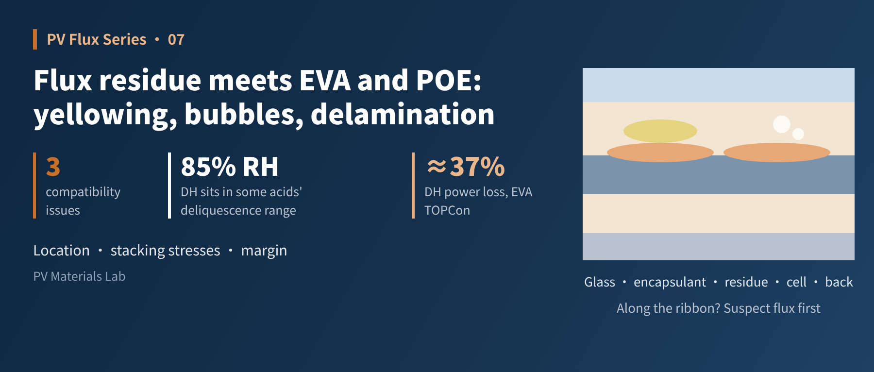
Flux residue in PV modules is never cleaned. After lamination it is sealed between glass and encapsulant for good, where it lives with moisture, acetic acid and UV light. Starting from this "sealed micro-environment", this article covers three typical compatibility problems: bubbles, yellowing and delamination. It explains how acetic acid from EVA and organic acid residue add up, uses research data to show why some organic acid activators "absorb water and turn into an electrolyte" at high humidity, discusses what switching to POE can and cannot fix, and closes with an approach to validating flux–encapsulant compatibility.
With this article we move into the reliability part of the series. Earlier articles kept returning to one fact: PV modules use no-clean flux. Nothing is washed after soldering, and the residue is sealed in permanently during lamination. So what happens between that residue and the encapsulant around it? This article is about compatibility between flux and encapsulation materials.
01The residue is locked into a sealed micro-environment
After lamination, the ribbon and its flux residue sit between the cell and the front encapsulant. Above them are the encapsulant and glass; below them the cell, the rear encapsulant and the backsheet or rear glass. That position means the residue faces several long-term influences:
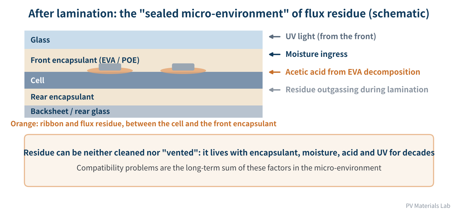
Figure 1. The "sealed micro-environment" of flux residue after lamination (schematic)
- Heat and vacuum during lamination: solvent or low-boiling components that have not fully evaporated from the residue may be released under heat and vacuum.
- Moisture in service: neither encapsulant nor backsheet is a perfect moisture barrier, so in damp heat, water gradually works its way into the module.
- Acetic acid from EVA: EVA slowly hydrolyses during damp-heat ageing and releases acetic acid, a widely recognised cause of module corrosion.
- UV light: the front encapsulant is exposed to UV for years, and both organic matter in the residue and additives in the encapsulant can undergo photochemical change.
The residue cannot be cleaned off, nor can it be "vented". Compatibility problems are therefore the long-term sum of several factors acting together in this micro-environment.
02Three typical compatibility problems
| Symptom | When it usually appears | Possible flux-related cause | Other factors to rule out |
|---|---|---|---|
| Bubbles | Right after lamination, or increasing after ageing | Too much flux or insufficient drying before soldering; volatile components in the residue released during lamination | Lamination parameters, damp encapsulant, foreign matter |
| Yellowing / discoloration | Mostly after UV or damp-heat ageing, concentrated near the ribbon | Organic matter in the residue reacting with encapsulant additives such as cross-linkers and antioxidants under light and heat | Ageing of the encapsulant formulation itself, backsheet yellowing |
| Delamination | After ageing, often running along the ribbon | Residue forms a weak boundary layer on the ribbon surface and reduces adhesion; moisture uptake at the interface weakens it further in damp heat | Insufficient cross-linking, ribbon surface condition |
Table 1. Three typical compatibility problems and what to check
All three share one feature: they tend to cluster around the ribbon. That is an important clue for telling "flux-related" apart from "encapsulant-only" problems. If yellowing or delamination follows the ribbon while areas away from it look normal, flux should be high on the list of suspects.
Location matters. Bubbles, yellowing or delamination that follow the ribbon point to flux residue first.
03Acetic acid from EVA meets organic acid residue: corrosion risks add up
Acetic acid from EVA is the classic mechanism behind damp-heat corrosion in modules. Work from the PV laboratory at EPFL in Switzerland treats corrosion as one of the main "wear-out" degradation modes at the end of a module's life: it develops slowly as moisture and acetic acid build up inside the module, and the team has designed tests that use acidic solutions to accelerate cell corrosion.
With TOPCon, the problem grows. A UNSW study published in 2025 in Solar Energy Materials and Solar Cells ran 85°C/85% RH damp heat on glass-backsheet TOPCon modules with EVA on both sides. After 1,000 hours, modules with conventional Ag/Al paste dropped from 581.9 W to 366.4 W, a relative power loss of 37.0%, while fill factor fell from 79.6% to 51.8% (a 34.9% relative drop). Modules made with low-Al Ag paste and laser-assisted firing (LAF) lost only 6.2%. The team attributed the failures to acetic acid from EVA hydrolysis, concluded that double-sided EVA is not currently suitable for glass-backsheet TOPCon modules, and called for improvements to both front and rear metallisation and to encapsulation materials.
Flux residue contains organic acids too. Near the ribbon and fingers, acetic acid and organic acid residue can therefore act as a "double acid source". Moisture is the key. An electronics study from the Technical University of Denmark (DTU) examined several weak organic acid activators common in no-clean fluxes and found that the humidity at which they start to "absorb water and dissolve" varies widely.
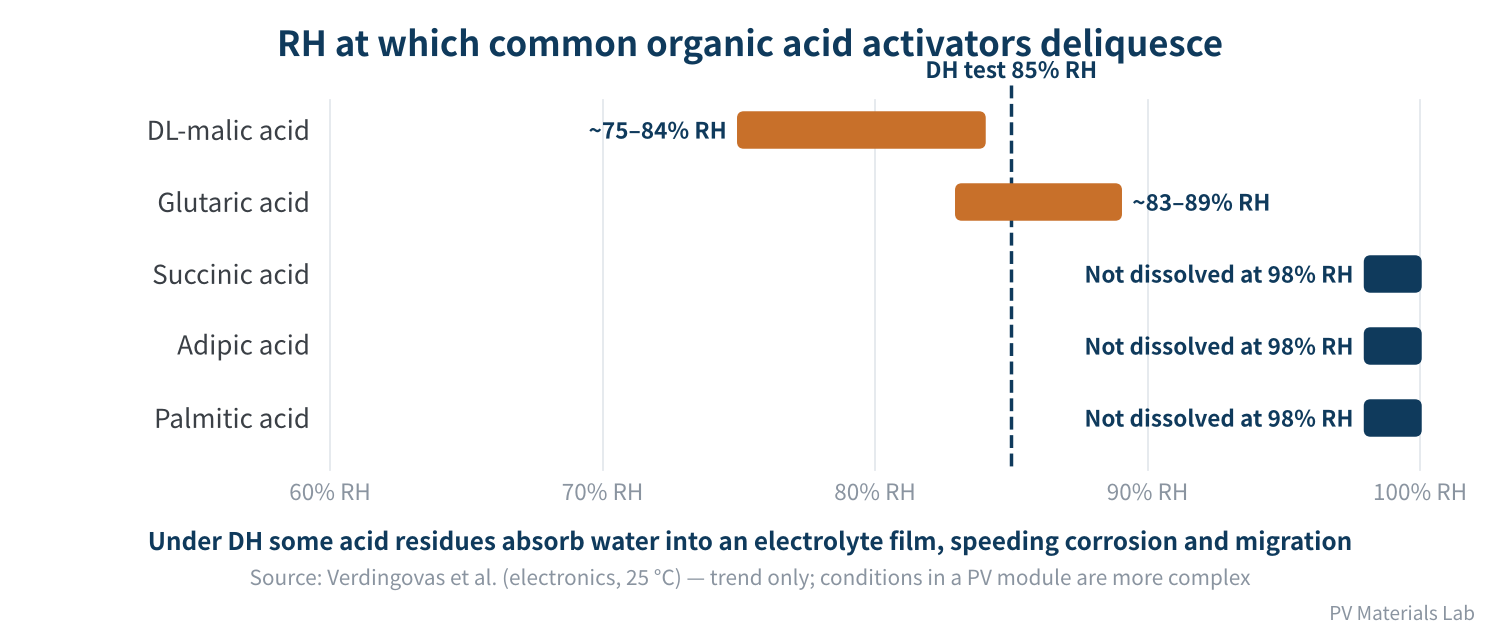
Figure 2. Relative humidity at which common organic acid activators start to deliquesce
- Malic and glutaric acid: according to the study, they start to deliquesce at about 75–84% RH and 83–89% RH respectively, forming an electrolyte film; leakage current rises sharply and electrochemical migration and corrosion appear.
- Succinic, adipic and palmitic acid: still not dissolved at 98% RH, with adipic and palmitic acid showing the lowest leakage current.
- Soldering heat helps, but is no cure-all: the study reports that heating samples at 220–245°C for 45 seconds reduced leakage current, especially for the more volatile glutaric and malic acids. Earlier work by the same group adds a caveat, however: after 250°C for 45 seconds, about 5% of the glutaric acid remained, and that remainder was still corrosive. Heat reduces the residue but does not necessarily remove the risk.
Module damp-heat testing runs at 85% RH, which falls right inside the range where some of these acids begin to deliquesce. The study was done on electronics PCBs, at a test temperature (25°C) and on a carrier quite different from a PV module, but the lesson is valuable: the choice of activator determines not only how well the joint solders, but also how "quiet" the residue stays in damp heat. This echoes article 02 of the series: ideally, the activator is fully consumed or evaporated during soldering.
04Does switching to POE solve everything?
Unlike EVA, POE does not hydrolyse into acetic acid, and its water vapour transmission is usually lower. That is why it is increasingly used in corrosion-sensitive modules such as TOPCon, and EVA/POE/EVA co-extruded (EPE) films are common as well. Switching to POE does remove acetic acid as a major stressor, but it does not solve everything:
- The residue is still acidic: organic acids in flux residue do not disappear when the encapsulant changes. The TOPCon and HJT corrosion studies discussed in article 06 looked precisely at the effect of flux alone on unencapsulated cells.
- The adhesion interface is still sensitive: the boundary layer residue forms on the ribbon can affect POE adhesion too. POE is non-polar and relies mainly on additives such as silane coupling agents for adhesion, so its process window differs from EVA's.
- There are more formulation combinations: EVA, POE and co-extruded films each use different additive packages from each supplier, so compatibility with a given flux has to be confirmed case by case rather than inferred. The outer layers of EPE are still EVA, so the acetic acid source has not fully gone away.
POE removes one acid source, but it does not exempt you from flux compatibility testing. Whenever either the flux or the encapsulant changes, re-confirm.
05How to validate flux–encapsulant compatibility
As far as we could find, there is no unified standard specifically for flux–encapsulant compatibility, and module makers usually design their own validation plans based on experience. We suggest the following approach:
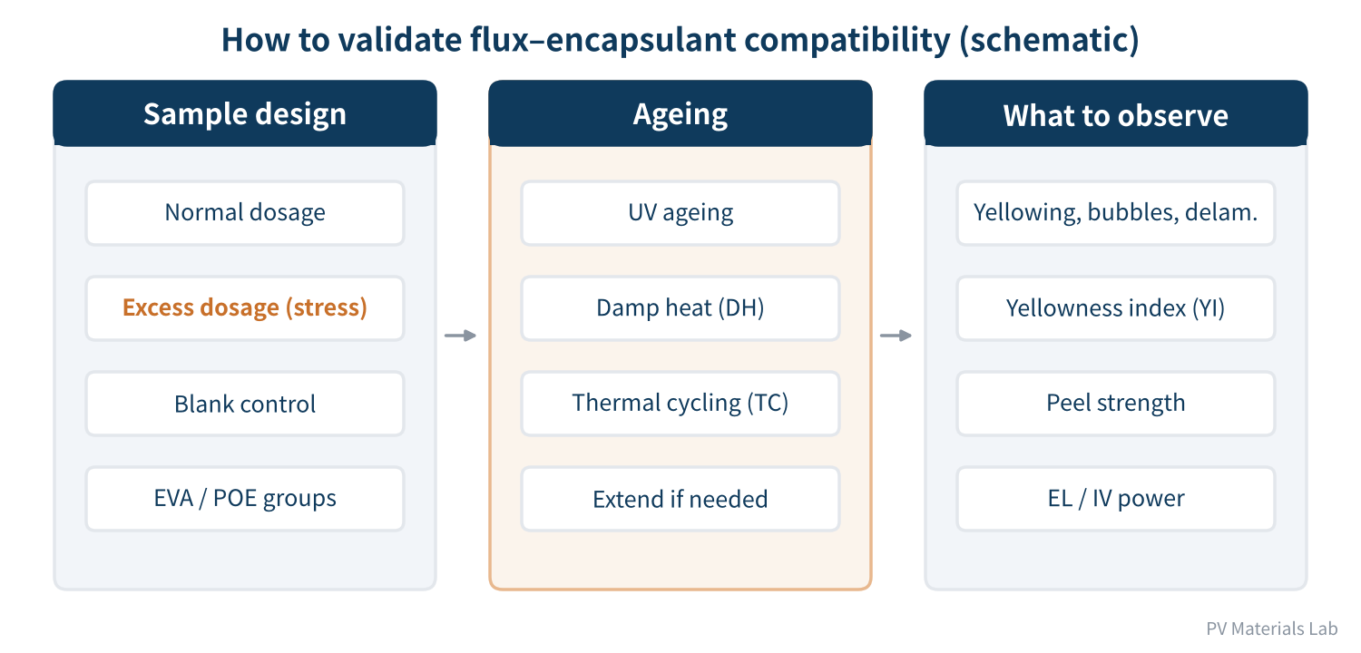
Figure 3. Approach to validating flux–encapsulant compatibility (schematic)
- Make samples realistic: use the ribbon, cells, flux and encapsulant from mass production, solder and laminate mini-modules or single-cell samples with the production process, rather than simply dropping flux onto encapsulant.
- Add a stress group: besides the normal-dose group, add samples with deliberately increased flux to simulate occasional over-application and overflow on the line. This group usually exposes problems best. Also keep a blank control with no flux or with flux removed.
- Test each encapsulant system: if the line uses EVA, POE or EPE in parallel, or plans to switch, validate each separately.
- Age and inspect: ageing can follow the UV preconditioning, damp-heat and thermal-cycling tests of IEC 61215-2:2021, extended as needed (for example 2,000–3,000 hours of damp heat). Inspect appearance (yellowing, bubbles, delamination), yellowness index, encapsulant-to-ribbon peel strength, EL and power change.
When judging results, focus on the differences between the stress group, the normal group and the control, not just on whether the normal group "passes". If the stress group shows clear yellowing or delamination around the ribbon, the compatibility margin between that flux and encapsulant is small, and flux dosage on the line must be controlled more tightly.
06Final thoughts
Three things to remember about flux–encapsulant compatibility:
- Look at location: bubbles, yellowing and delamination that follow the ribbon are a strong clue to a flux-related problem;
- Look at stacking stresses: acetic acid from EVA, organic acids in the residue and ingressing moisture add up, and some activators turn into an electrolyte at 85% RH;
- Look at margin: include an over-dosed stress group in compatibility testing, and re-confirm whenever the encapsulant or flux changes. POE is no exception.
Compatibility problems ultimately show up as visual defects or power loss in modules. On the production line, though, what people usually meet first are soldering defects: cold joints, over-soldering, low peel strength, blackened joints. In the next article we switch to the line's perspective and look at how to troubleshoot common soldering defects: how to tell whether the problem lies in the flux, or in the ribbon, the cells or the equipment settings.
Have you seen yellowing or delamination running along the ribbon? Did you find the cause? We would be glad to hear from you.
References
- X. Wu, B. Hoex et al.: Is TOPCon ready for EVA? Insights from damp heat testing of glass-backsheet modules, Solar Energy Materials and Solar Cells 288 (2025) 113650, DOI: 10.1016/j.solmat.2025.113650, https://www.sciencedirect.com/science/article/pii/S092702482500251X
- pv magazine: EVA-induced degradation has significant impact on power losses in TOPCon solar modules, 2025-04-22, https://www.pv-magazine.com/2025/04/22/eva-induced-degradation-has-significant-impact-on-power-losses-in-topcon-solar-modules/
- A. Fairbrother, L. Gnocchi, C. Ballif, A. Virtuani: Corrosion testing of solar cells: Wear-out degradation behavior, Solar Energy Materials and Solar Cells 248 (2022)
- V. Verdingovas, M. S. Jellesen, R. Ambat: Solder Flux Residues and Humidity-Related Failures in Electronics: Relative Effects of Weak Organic Acids Used in No-Clean Flux Systems, Journal of Electronic Materials 44(4) (2015) 1116–1127, DOI: 10.1007/s11664-014-3609-0, https://orbit.dtu.dk/en/publications/solder-flux-residues-and-humidity-related-failures-in-electronics/
- H. Conseil, M. S. Jellesen, R. Ambat et al.: study on the corrosivity of weak organic acid residues after soldering heat, EUROCORR, 2013
- pv magazine: UNSW study shows impact of soldering flux on TOPCon solar cell degradation, 2025
- G. Park et al.: Soldering flux causes corrosion of indium tin oxide electrode in heterojunction solar cells, Cell Reports Physical Science, 2025, https://www.sciencedirect.com/science/article/pii/S2666386425002188
- IEC 61215-2:2021, Terrestrial photovoltaic (PV) modules — Design qualification and type approval — Part 2: Test procedures
A PV R&D and technology team with 10+ years of experience | In-depth technical knowledge sharing
Materials · Reliability · Failure Analysis · Standards & Certification · Products · Processes
Exploring AI + PV; collaboration welcome
Disclaimer:
1. Original content reflects the authors' personal views only, is for reference only and does not constitute investment advice.
2. Reposted and cited content is credited to its source, out of respect for original work.
3. Some content was produced with AI assistance (chart generation, data retrieval, concept explanations, etc.); the core framework and key content were written by our technical team and reviewed by people.
4. If anything is inaccurate or infringes your rights, please leave a message or contact us and we will deal with it.